Gigabyte GA-P55-USB3 Manual - Page 52
Onboard SATA/IDE Ctrl Mode GIGABYTE SATA2, IDE and GSATA2_6/7 Connectors - windows 10
 |
UPC - 818313009777
View all Gigabyte GA-P55-USB3 manuals
Add to My Manuals
Save this manual to your list of manuals |
Page 52 highlights
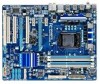
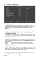
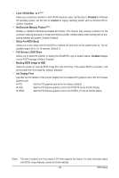
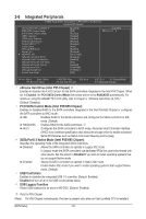
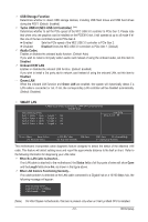
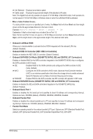
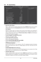
Link Detected Displays transmission speed. Cable Length Displays the approximate length of the attached LAN cable. Note: The Gigabit hub will only operate at a speed of 10/100 Mbps in MS-DOS mode; it will operate at a normal speed of 10/100/1000 Mbps in Windows mode or when the LAN Boot ROM is activated. When a Cable Problem Occurs... If a cable problem occurs on a specified pair of wires, the Status field will show Short and then length shown will be the approximate distance to the fault or short. Example: Part1-2 Status = Short / Length = 2m Explanation: A fault or short might occur at about 2m on Part 1-2. Note: Part 4-5 and Part 7-8 are not used in a 10/100 Mbps environment, so their Status fields will show Open, and the length shown is the approximate length of the attached LAN cable. Onboard LAN Boot ROM Allows you to decide whether to activate the boot ROM integrated with the onboard LAN chip. (Default: Disabled) Onboard USB 3.0 Controller (NEC USB 3.0 Controller) Enables or disables the NEC USB 3.0 controller. (Default: Enabled) Onboard SATA/IDE Ctrl Mode (GIGABYTE SATA2, IDE and GSATA2_6/7 Connectors) Enables or disables RAID for the SATA controller integrated in the GIGABYTE SATA2 chip or configures the SATA controller to AHCI mode. IDE Disables RAID for the SATA controller and configures the SATA controller to IDE mode. (Default) AHCI Configures the SATA controller to AHCI mode. Advanced Host Controller Interface (AHCI) is an interface specification that allows the storage driver to enable advanced Serial ATA features such as Native Command Queuing and hot plug. RAID/IDE Enables RAID for the SATA controller; the IDE controller still operates in IDE mode. Onboard SATA/IDE Device (GIGABYTE SATA2, IDE and GSATA2_6/7 Connectors) Enables or disables the IDE and SATA controllers integrated in the GIGABYTE SATA2 chip. (Default: Enabled) Onboard Serial Port 1 Enables or disables the first serial port and specifies its base I/O address and corresponding interrupt. Options are: Auto, 3F8/IRQ4 (default), 2F8/IRQ3, 3E8/IRQ4, 2E8/IRQ3, Disabled. Onboard Parallel Port Enables or disables the onboard parallel port (LPT) and specifies its base I/O address and corresponding interrupt. Options are: 378/IRQ7 (default), 278/IRQ5, 3BC/IRQ7, Disabled. Parallel Port Mode Selects an operating mode for the onboard parallel (LPT) port. Options are: SPP (Standard Parallel Port) (default), EPP (Enhanced Parallel Port), ECP (Extended Capabilities Port), ECP+EPP. BIOS Setup - 52 -
-
 1
1 -
2
-
3
-
4
-
5
-
6
-
7
-
8
-
9
-
10
-
11
-
12
-
13
-
14
-
15
-
16
-
17
-
18
-
19
-
20
-
21
-
22
-
23
-
24
-
25
-
26
-
27
-
28
-
29
-
30
-
31
-
32
-
33
-
34
-
35
-
36
-
37
-
38
-
39
-
40
-
41
-
42
-
43
-
44
-
45
-
46
-
 47
47 -
 48
48 -
 49
49 -
 50
50 -
 51
51 -
 52
52 -
 53
53 -
 54
54 -
 55
55 -
 56
56 -
 57
57 -
58
-
59
-
60
-
61
-
62
-
63
-
64
-
65
-
66
-
67
-
68
-
69
-
70
-
71
-
72
-
73
-
74
-
75
-
76
-
77
-
78
-
79
-
80
-
81
-
82
-
83
-
84
-
85
-
86
-
87
-
88
-
89
-
90
-
91
-
92
-
93
-
94
-
95
-
96
-
97
-
98
-
99
-
100
-
101
-
102
-
103
-
104
-
105
-
106
-
107
-
108
-
109
-
110
-
111
-
112
-
113
-
114
-
115
-
116
-
117
-
118
-
119
-
120
-
121
-
122
-
123
-
124
-
125
-
126
-
127
-
128
 |
 |