Gigabyte GA-SBC7100 User Manual - Page 11
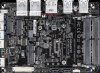
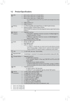
SYS_FAN Fan Header, SATA3 0/1 SATA 6Gb/s Connectors, SATA_PWR SATA Power Connector
 |
View all Gigabyte GA-SBC7100 manuals
Add to My Manuals
Save this manual to your list of manuals |
Page 11 highlights
1) SYS_FAN (Fan Header) The fan header on this motherboard is 4-pin. The fan header possesses a foolproof insertion design. When connecting a fan cable, be sure to connect it in the correct orientation (the black connector wire is the ground wire). The speed control function requires the use of a fan with fan speed control design. For optimum heat dissipation, it is recommended that a system fan be installed inside the chassis. Pin No. Definition 1 GND 1 2 Voltage Speed Control 3 Sense 4 PWM Speed Control •• Be sure to connect fan cables to the fan headers to prevent your system from overheating. Overheating may result in damage to the system may hang. •• The fan header is not configuration jumper blocks. Do not place a jumper cap on the header. 2) SATA3 0/1 (SATA 6Gb/s Connectors) The SATA connectors conform to SATA 6Gb/s standard and are compatible with SATA 3Gb/s and SATA 1.5Gb/s standard. Each SATA connector supports a single SATA device. 7 Pin No. Definition 1 GND 2 TXP 3 TXN 4 GND 5 RXN 6 RXP 7 GND 1 3) SATA_PWR (SATA Power Connector) The connector provides power to installed SATA device. Pin No. Definition 1 GND 1 2 VCC 3 +12V 4 GND - 11 - eDP
-
 1
1 -
2
-
3
-
4
-
5
-
 6
6 -
 7
7 -
 8
8 -
 9
9 -
 10
10 -
 11
11 -
 12
12 -
 13
13 -
 14
14 -
 15
15 -
 16
16 -
17
-
18
-
19
-
20
-
21
-
22
-
23
-
24
-
25
-
26
-
27
-
28
-
29
-
30
-
31
 |
 |
