Gigabyte GA-SBC7100 User Manual - Page 13
DCIN_PWR DC Power Connector, Input 9V ~ 36V, FPD Flat Panel Display Header
 |
View all Gigabyte GA-SBC7100 manuals
Add to My Manuals
Save this manual to your list of manuals |
Page 13 highlights
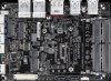
6) DCIN_PWR (DC Power Connector, Input 9V ~ 36V) Pin No. Definition 1 GND 1 2 DC IN 3 DC IN 4 GND eDP eDP eDP 7) FPD (Flat Panel Display Header) The FPD is a high-speed interface connecting the output of a video controller in a laptop computer, computer monitor or LCD television set to the display panel. Most laptops, LCD computer monitors and LCD TVs use this interface internally. The header conforms to FPD specification. Pin No. Definition Pin No. Definition 87 1 BKLT_EN 5 BKLT_GND/Brightness_GND 2 BKLT_PWM 6 BKLT_GND/Brightness_GND 21 3 BKLT_PWR (FPD_PWR) 7 Brightness_Up 4 BKLT_PWR (FPD_PWR) 8 Brightness_Down 8) F_USB1/F_USB2 (USB 2.0/1.1 Headers) The headers conform to USB 2.0/1.1 specification. Each USB header can provide two USB ports via an optional USB bracket. For purchasing the optional USB bracket, please contact the local dealer. 10 9 2 1 Pin No. 1 2 3 4 5 Definition Power (5V) Power (5V) USB DXUSB DYUSB DX+ Pin No. 6 7 8 9 10 Definition USB DY+ GND GND No Pin NC •• Do not plug the IEEE 1394 bracket (2x5-pin) cable into the USB header. •• Prior to installing the USB bracket, be sure to turn off your computer and unplug the power cord from the power outlet to prevent damage to the USB bracket. 9) AUDIO (Front Panel Audio Header) The front panel audio header supports High Definition audio (HD). You may connect your chassis front panel audio module to this header. Make sure the wire assignments of the module connector match the pin assignments of the motherboard header. Incorrect connection between the module connector and the motherboard header will make the device unable to work or even damage it. 10 9 21 Pin No. 1 2 3 4 5 Definition LINE_R MIC_R GND GND LINE_L Pin No. 6 7 8 9 10 Definition MIC_L GND GND RSV RSV Some chassis provide a front panel audio module that has separated connectors on each wire instead of a single plug. For information about connecting the front panel audio module that has different wire assignments, please contact the chassis manufacturer. - 13 -
-
 1
1 -
2
-
3
-
4
-
5
-
6
-
7
-
 8
8 -
 9
9 -
 10
10 -
 11
11 -
 12
12 -
 13
13 -
 14
14 -
 15
15 -
 16
16 -
 17
17 -
 18
18 -
19
-
20
-
21
-
22
-
23
-
24
-
25
-
26
-
27
-
28
-
29
-
30
-
31
 |
 |
