Gigabyte GA-VM900M Manual
Gigabyte GA-VM900M Manual
 |
View all Gigabyte GA-VM900M manuals
Add to My Manuals
Save this manual to your list of manuals |
Gigabyte GA-VM900M manual content summary:
- Gigabyte GA-VM900M | Manual - Page 1
GA-VM900M Intel® CoreTM 2 Duo / Intel® Pentium® D / Intel® Pentium® 4 / Celeron® D LGA775 Processor Motherboard User's Manual Rev. 2001 12ME-VM900M-2001R * The WEEE marking on the product indicates this product must not be disposed of with user's other household waste and must be handed over - Gigabyte GA-VM900M | Manual - Page 2
Motherboard GA-VM900M Jun. 22, 2007 Motherboard GA-VM900M Jun. 22, 2007 - Gigabyte GA-VM900M | Manual - Page 3
following: „ For detailed product information and specifications, please carefully read the "Product User Manual". „ For detailed information related to Gigabyte's unique features, please go to "Technology Guide" section on Gigabyte's website to read or download the information you need. For more - Gigabyte GA-VM900M | Manual - Page 4
Box Contents ...6 OptionalItems ...6 GA-VM900M Motherboard Layout 7 Block Diagram ...8 Chapter 1 Hardware Installation 9 1-1 Considerations Prior to Installation 9 1-2 Feature Summary 10 1-3 Installation of the CPU and CPU Cooler 12 1-3-1 Installation of the CPU 12 1-3-2 Installation of the - Gigabyte GA-VM900M | Manual - Page 5
Introduction 50 4-1-3 Flash BIOS Method Introduction 52 4-1-4 Configuring SATA Hard Drive(s 56 4-1-5 2- / 4- / 5.1- / 7.1- Channel Audio Introduction 67 4-2 Troubleshooting 72 4-2-1 Frequently Asked Questions 72 4-2-2 Troubleshooting Procedure 73 4-3 Windows Vista ReadyBoost 75 - 5 - - Gigabyte GA-VM900M | Manual - Page 6
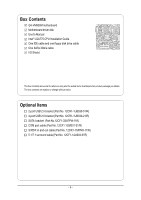
Box Contents GA-VM900M motherboard Motherboard driver disk User's Manual Intel® LGA775 CPU Installation Guide One IDE cable and one floppy disk drive cable One SATA 3Gb/s cable I/O Shield The box contents above are for reference only and the actual items shall depend on product package you obtain. - Gigabyte GA-VM900M | Manual - Page 7
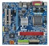
GA-VM900M Motherboard Layout KB_MS LGA775 CPU_FAN DDRII_1 DDRII_2 ATX FDD VGA COMA LPT ATX_12V USB GA-VM900M LAN USB AUDIO F_AUDIO PCIE_16 RTL8201 PCIE_1 PCI1 CD_IN PCI2 CODEC HDA_SUR SPDIF_IO Winbond W83627 VIA P4M900 BIOS CLR_CMOS COMB CI IDE1 IDE2 SYS _FAN VIA VT8237S - Gigabyte GA-VM900M | Manual - Page 8
/Mouse ATA-133/100/66/33 IDE Channel BIOS Winbond W83627 Floppy LPT Port COM Ports PCI CLK (33 MHz) Surround Speaker Out Center/Subwoofer Speaker Out Side Speaker Out MIC Line-Out Line-In SPDIF In SPDIF Out (Note) Use of a 1066/800 MHz FSB CPU is required if you wish to - Gigabyte GA-VM900M | Manual - Page 9
instructions below: 1. Please turn off the computer and unplug its power cord. 2. When handling the motherboard , avoid touching any metal leads or connectors. 3. It is best to wear an electrostatic discharge (ESD) cuff when handling electronic components (CPU motherboard problem manual - Gigabyte GA-VM900M | Manual - Page 10
with CPU Front Side Bus Š Supports 1066/800/533 MHz FSB Chipset Š Northbridge: VIA P4M900 Chipset Š Southbridge: VIA VT8237S LAN Š Onboard Realtek RTL8201 chip (10/100 Mbit) Audio Š Onboard VIA VT1708A chip Š Supports High Definition Audio Š Supports 2 / 4 / 5.1 / 7.1-channel audio (Note - Gigabyte GA-VM900M | Manual - Page 11
failure warning Š CPU smart fan control (Note 4) BIOS Š 1 4 Mbit flash ROM Š Use of licensed AWARD BIOS Š PnP 1.0a, DMI 2.0, SM BIOS 2.3, ACPI 1.0b Additional Features Š Supports @BIOS Š Supports Download Center Š Supports Q-Flash Š Supports EasyTune (only supports Hardware Monitor function - Gigabyte GA-VM900M | Manual - Page 12
your thumb and forefinger, carefully place it into the socket in a straight and downwards motion. Avoid twisting or bending motions that might cause damage to the CPU during installation.) GA-VM900M Motherboard - 12 - Fig. 4 Once the CPU is properly inserted, please replace the load plate and - Gigabyte GA-VM900M | Manual - Page 13
make sure the Male and Female push pin are joined closely. (for detailed installation instructions, please refer to the CPU cooler installation section of the user manual) Fig. 5 Please check the back of motherboard after installing. If the push pin is inserted as the picture, the installation is - Gigabyte GA-VM900M | Manual - Page 14
only fit in one direction. Insert the DIMM memory module vertically into the DIMM socket. Then push it down. Fig.2 Close the plastic clip at both edges of the DIMM sockets to lock the DIMM module. Reverse the installation steps when you wish to remove the DIMM module. GA-VM900M Motherboard - 14 - - Gigabyte GA-VM900M | Manual - Page 15
an expansion slot that supports your card. Remove the BIOS changes for your expansion card(s). 7. Install the driver provided with the expansion card in your operating system. Example: Installing and Removing a PCI Express x16 Graphics Card: • Installing a Graphics Card: Gently insert the graphics - Gigabyte GA-VM900M | Manual - Page 16
need to install a 5.1/7.1 surround cable (optional) and enable the multi-channel audio feature through the audio driver. Refer to the instructions on setting up a 2/4/5.1/7.1-channel audio configuration in Chapter 4, "Configuring 2/4/5.1/7.1Channel Audio Introduction." GA-VM900M Motherboard - 16 - - Gigabyte GA-VM900M | Manual - Page 17
English 1-7 Connectors Introduction 3 2 5 1 6 10 4 7 11 18 9 13 8 12 15 16 17 14 1) ATX_12V 2) ATX (Power Connector) 3) CPU_FAN 4) SYS_FAN 5) FDD 6) IDE1 / IDE2 7) SATAII0 / SATAII1 8) F_PANEL 9) PWR_LED 10) F_AUDIO 11) CD_IN 12) SPDIF_IO 13) HDA_SUR 14) F_USB1 / F_USB2 15) COMB 16) - Gigabyte GA-VM900M | Manual - Page 18
Align the power connector with its proper location on the motherboard and connect tightly. The ATX_12V power connector mainly supplies power to the CPU. If the ATX_12V power connector is not connected, the system +5V +5V (Only for 24-pin ATX) GND(Only for 24-pin ATX) GA-VM900M Motherboard - 18 - - Gigabyte GA-VM900M | Manual - Page 19
ground wire (GND). Remember to connect the CPU/system fan cable to the CPU_FAN/SYS_FAN connector to prevent CPU damage or system hanging caused by overheating. 1 cable while the other end of the cable connects to the FDD drive. The types of FDD drives supported are: 360 KB, 720 KB, 1.2 MB, 1.44 MB - Gigabyte GA-VM900M | Manual - Page 20
0 and RAID 1. Refer to Chapter 4, "Configuring SATA Hard Drive(s)," for instructions on configuring a RAID array. SATAII1 7 1 1 7 SATAII0 Pin No. 1 2 3 4 5 6 7 Definition GND TXP TXN GND RXN RXP GND A RAID 0 or RAID 1 configuration requires two hard drives. GA-VM900M Motherboard - 20 - - Gigabyte GA-VM900M | Manual - Page 21
English 8) F_PANEL (Front Panel Connector) Please connect the power LED, PC speaker, reset switch and power switch etc. of your chassis front panel to the F_PANEL connector according to the pin assignments below. Message LED/ Power/ Sleep LED Speaker Connector Power Switch MSG+ MSG- PW+ PWSPEAK+ - Gigabyte GA-VM900M | Manual - Page 22
5 Line Out (R) 6 NC 7 NC 8 No Pin 9 Line Out (L) 10 NC By default, the audio driver is configured to support HD Audio. To connect an AC'97 front panel audio module to this connector, please refer to the instructions on page 71 about the software settings. GA-VM900M Motherboard - 22 - - Gigabyte GA-VM900M | Manual - Page 23
. Pin No. Definition 1 CD-L 1 2 GND 3 GND 4 CD-R 12) SPDIF_IO (S/PDIF In/Out connector, red) The S/PDIF output is capable of providing digital audio to external speakers or compressed AC3 data to an external Dolby Digital Decoder. Use this feature only when your stereo system has digital - Gigabyte GA-VM900M | Manual - Page 24
Center Connector) To enable 7.1-channel audio, connect a 5.1/7.1 surround cable to this header and configure audio output mode via the audio software. For purchasing the optional 8 9 10 Definition Power(5V) Power(5V) USB0 DXUSB1 DYUSB0 DX+ USB1 DY+ GND GND No Pin NC GA-VM900M Motherboard - 24 - - Gigabyte GA-VM900M | Manual - Page 25
local dealer. 2 10 1 9 Pin No. 1 2 3 4 5 6 7 8 9 10 Definition NDCDBNSINB NSOUTB NDTRBGND NDSRBNRTSBNCTSBNRIBNo Pin 16) CI (Chassis Intrusion Header) This motherboard provides a chassis detection feature that detects if the chassis cover has been removed. This function requires a chassis with - Gigabyte GA-VM900M | Manual - Page 26
Open: Normal Short: Clear CMOS 18) BATTERY GA-VM900M Motherboard Danger of explosion if battery is incorrectly replaced. Replace only with the same or equivalent type recommended by the manufacturer. Dispose of used batteries according to the manufacturer's instructions. If you want to erase CMOS - Gigabyte GA-VM900M | Manual - Page 27
BIOS, either GIGABYTE's Q-Flash or @BIOS utility can be used. Q-Flash allows the user to quickly and easily update or backup BIOS without entering the operating system. @BIOS is a Windows-based utility that does not require users to boot to DOS before upgrading BIOS but directly download and update - Gigabyte GA-VM900M | Manual - Page 28
the BIOS Setup when somehow the system is not stable as usual. This action makes the system reset to the default settings for stability. 3. The BIOS Setup menus described in this chapter are for reference only and may differ from the exact settings for your motherboard. GA-VM900M Motherboard - 28 - Gigabyte GA-VM900M | Manual - Page 29
English „ Standard CMOS Features This setup page includes all the items in standard compatible BIOS. „ Advanced BIOS Features This setup page includes all the items of Award special enhanced features. „ Integrated Peripherals This setup page includes all onboard peripherals. „ Power Management - Gigabyte GA-VM900M | Manual - Page 30
IDE Drive You can use one of the two methods: • Auto Allows BIOS to automatically detect IDE/SATA devices during POST(default) • None Select this if no IDE/SATA devices are used and the system will skip the automatic detection step and allow for faster system start up. GA-VM900M Motherboard - Gigabyte GA-VM900M | Manual - Page 31
of the base memory is typically 512 K for systems with 512 K memory installed on the motherboard, or 640K for systems with 640 K or more memory installed on the motherboard. Extended Memory The BIOS determines how much extended memory is present during the POST. This is the amount of memory - Gigabyte GA-VM900M | Manual - Page 32
the list. Press to exit this menu. First / Second / Third Boot Device Floppy LS120 Select your boot device priority by Floppy. Select your boot device priority by LS120. (Note) This item will show up when you install a processor which supports this function. GA-VM900M Motherboard - 32 - Gigabyte GA-VM900M | Manual - Page 33
operating system with multi processors mode supported. Disabled (Default value) Disable CPU Hyper Threading. Limit CPUID Max. to 3 (Note) Enabled Disabled Limit CPUID Maximum value to 3 when use older OS like NT4. Disable CPUID Limit for windows XP. (Default value) No-Execute Memory Protect - Gigabyte GA-VM900M | Manual - Page 34
Support USB Mouse Support channel IDE port. (Default value) Disabled Disable the onboard 1st channel audio function. (Default value) Disabled Disable this function. LAN Controller Enabled Enable the onboard LAN function. (Default value) Disabled Disable this function. GA-VM900M Motherboard - Gigabyte GA-VM900M | Manual - Page 35
Support Enabled Disabled Enable the USB keyboard support. Disable this function. (Default value) USB Mouse Support Enabled Disabled Enable the USB mouse support storage devices, including USB flash drives and USB hard drives during POST. Enabled Disabled BIOS will scan all USB storage devices - Gigabyte GA-VM900M | Manual - Page 36
Port Mode option is set to EPP or ECP+EPP mode. EPP1.7 Set LPT port use EPP 1.7. (Default value) EPP1.9 Set LPT port use EPP 1.9. GA-VM900M Motherboard - 36 - - Gigabyte GA-VM900M | Manual - Page 37
" button, you can press the key to power on the system. Any Key Press any keys on your keyboard to power on the system. - 37 - BIOS Setup - Gigabyte GA-VM900M | Manual - Page 38
alarm function to POWER ON system. If Resume by Alarm is Enabled. Date (of Month) : Everyday, 1~31 Resume Time (hh: mm: ss) : (0~23) : (0~59) : (0~59) GA-VM900M Motherboard - 38 - - Gigabyte GA-VM900M | Manual - Page 39
IRQ 3,4,5,7,9,10,11,12,14,15 to PCI 1. Auto assign IRQ to PCI 2. (Default value) Set IRQ 3,4,5,7,9,10,11,12,14,15 to PCI 2. - 39 - BIOS Setup - Gigabyte GA-VM900M | Manual - Page 40
system/CPU temperature at 80oC / 176oF. Monitor system/CPU temperature at 90oC / 194oF. Disable this function. (Default value) SYS/CPU FAN Fail Warning Disabled Enabled Disable the fan fail warning function. (Default value) Enable the fan fail warning function. GA-VM900M Motherboard - 40 - Gigabyte GA-VM900M | Manual - Page 41
English CPU Smart FAN Control Disabled Disable this function. Enabled When this function is enabled, CPU fan will run at different speed depending on CPU temperature. Users can adjust the fan speed with EasyTune based on their requirements. (Default value) - 41 - BIOS Setup - Gigabyte GA-VM900M | Manual - Page 42
-Copyright (C) 1984-2007 Award Software ` Standard CMOS Features ` Advanced BIOS Features ` Integrated Peripherals ` Power Management Setup ` PnP/PCI Configurations loads the factory defaults for BIOS and Chipset Features which the system automatically detects. GA-VM900M Motherboard - 42 - - Gigabyte GA-VM900M | Manual - Page 43
the system will boot and you can enter Setup freely. The BIOS Setup program allows you to specify two separate passwords: SUPERVISOR PASSWORD and only basic items. If you select "System" at "Password Check" in Advance BIOS Features Menu, you will be prompted for the password every time the system is - Gigabyte GA-VM900M | Manual - Page 44
Saving CMOS Setup Utility-Copyright (C) 1984-2007 Award Software ` Standard CMOS Features ` Advanced BIOS Features ` Integrated Peripherals ` Power Management Setup ` PnP/PCI Configurations ` PC Health Status saving to RTC CMOS. Type "N" will return to Setup Utility. GA-VM900M Motherboard - 44 - - Gigabyte GA-VM900M | Manual - Page 45
other drivers. • After the drivers are installed, follow the onscreen instructions to restart your system. You can install other applications included in the motherboard driver disk. • For USB 2.0 driver support under the Windows XP operating system, please install the Windows XP Service Pack - Gigabyte GA-VM900M | Manual - Page 46
all the tools and applications that GIGABYTE develops and some free software. You may press the Install button following an item to install it. 3-3 Driver CD Information This page provides information about the drivers, applications and tools in this driver disk. GA-VM900M Motherboard - 46 - - Gigabyte GA-VM900M | Manual - Page 47
English 3-4 Hardware Information This page provides information about the hardware devices on this motherboard. 3-5 Contact Us Check the contacts information of the GIGABYTE headquarter in Taiwan and the overseas branch offices on the last page of this manual. - 47 - Drivers Installation - Gigabyte GA-VM900M | Manual - Page 48
English GA-VM900M Motherboard - 48 - - Gigabyte GA-VM900M | Manual - Page 49
of both CPU cooling fan and North-Bridge Chipset cooling fan, 4) PC health for monitoring system status.(Note) User Interface Overview Button/Display 1. OVERCLOCKING 2. C.I.A./M.I.B. 3. SMART FAN 4. PC HEALTH 5. GO 6. EASY MODE/ADVANCED MODE 7. Display Field 8. Function LEDs 9. GIGABYTE Logo 10 - Gigabyte GA-VM900M | Manual - Page 50
Supporting Microsoft operating systems including Windows XP -supported VGA BIOS Setup, go to Advanced BIOS Feature and set to boot from CD-ROM. Save the settings and exit the BIOS Setup. Insert the provided driver CD into your CD-ROM drive drivers as well as software. GA-VM900M Motherboard - 50 - - Gigabyte GA-VM900M | Manual - Page 51
Windows 2000, be sure to execute the EnableBigLba.exe program from the driver CD before data backup. 2. It is normal that data backup takes longer time than data restoration. 3. Xpress Recovery2 is compliant with the GPL regulations. 4. On a few motherboards based on Nvidia chipsets, BIOS update - Gigabyte GA-VM900M | Manual - Page 52
to update BIOS: 1. From GIGABYTE's website, download the latest compressed BIOS update file that matches your motherboard model 2. Extract the downloaded BIOS files and save the new BIOS file (e.g. VM900M.FA) to your floppy disk or hard disk. Note: Q-Flash only supports hard disks or flash drives - Gigabyte GA-VM900M | Manual - Page 53
the system when the system is reading/updating the BIOS. 2. Do not remove the floppy disk or hard drive/USB drive when the system is updating the BIOS. Step 3: When the update process is complete, press any key to return to the Q-Flash main menu. Q-Flash Utility v2.02 Flash Type/Size MXIC SPI - Gigabyte GA-VM900M | Manual - Page 54
Update" icon b. Click "Update New BIOS" c. Please select "All Files" in dialog box while opening the old file. d. Please search for BIOS unzip file, downloading from internet or any other methods (such as: VM900M.FA). e. Complete update process following the instruction. GA-VM900M Motherboard - Gigabyte GA-VM900M | Manual - Page 55
II, be sure that motherboard's model name in BIOS unzip file are the same as your motherboard's. Otherwise, your system won't boot. III. In method I, if the BIOS file you need cannot be found in @BIOSTM server, please go onto Gigabyte's web site for downloading and updating it according to method - Gigabyte GA-VM900M | Manual - Page 56
you may prepare only one hard drive. (b) An empty formatted floppy disk. (Note) (c) Windows Vista/XP/2000 setup disk. (d) Driver CD for your motherboard. (1) Install SATA hard drive(s) in your system Attach one create RAID. (Note) Required for setting up RAID array. GA-VM900M Motherboard - 56 - - Gigabyte GA-VM900M | Manual - Page 57
motherboard you have and the BIOS version. Step 2: Set First Boot Device under the Advanced BIOS Features menu to CDROM to boot from Windows installation CD (Figure 2). CMOS Setup Utility-Copyright (C) 1984-2007 Award Software Advanced BIOS Features Init Display First Dual display function VGA - Gigabyte GA-VM900M | Manual - Page 58
VT8237S V-RAID CDROM BOOT BIOS V1.20 Copyright (C) VIA Technologies Window! Figure 3 --SATA mode --SATA mode Step 2: In the RAID BIOS V1.20 X Create Array X Delete Array X Select/Clear Boot Array X Serial Number View Dev. Posi. Channel0 Master Channel1 Master Drive GA-VM900M Motherboard - 58 - - Gigabyte GA-VM900M | Manual - Page 59
V1.20 X Auto Setup For Data Security X Array Mode RAID 1 (Mirroring) X Select Disk Drives X Start Create Process Dev. Posi. Channel0 Master Channel1 Master Drive And the RAID mode selection menu will appear (Figure 6). The supported RAID modes include RAID 0 for performance, RAID 1 for data - Gigabyte GA-VM900M | Manual - Page 60
manually. Auto Setup allows BIOS to assign the hard drives and create arrays automatically. It is recommended all hard drives are new ones when you want to create an array. To manually V-RAID Utility V1.20 X Auto Setup drive will be destroyed after the array creation. GA-VM900M Motherboard - 60 - - Gigabyte GA-VM900M | Manual - Page 61
status on the lower screen. If there are no disk arrays then nothing will be displayed on the screen (Figure 9). VIA VT8237S V-RAID Utility V1.20 X Create Array X Delete Array X Select/Clear Boot Array X Serial Number View View Array/Disks Status.. F1 : K, L : Enter : ESC : View Array/disk Status - Gigabyte GA-VM900M | Manual - Page 62
up, press Y to confirm or press N to cancel (Figure 12). VIA VT8237S V-RAID Utility V1.20 X Create Array X Delete Array X Select/Clear Boot Array X Serial Number View Data on the two hard drives will be reserved and the two hard drives will become two normal drives. GA-VM900M Motherboard - 62 - - Gigabyte GA-VM900M | Manual - Page 63
recognized during the Windows setup process. First of all, copy the driver for the SATA controller from the motherboard driver CD-ROM to a floppy disk. See the instructions below about how to copy the driver in MS-DOS mode . (Note) Prepare a startup disk that has CD-ROM support and a blank formatted - Gigabyte GA-VM900M | Manual - Page 64
manufacturer, press S. * If you do not have any device support disks from a mass storage device manufacturer, or do not want to specify additional mass storage devices for use with Windows, press ENTER. S=Specify Additional Device ENTER=Continue F3=Exit Figure 17 GA-VM900M Motherboard - 64 - - Gigabyte GA-VM900M | Manual - Page 65
from the floppy disk. The driver installation will be finished in about one minute. Windows Setup Setup will load support for the following mass storage device(s): VIA V-RAID Controller Series (Windows XP/SRV2003) * To specify additional SCSI adapters, CD-ROM drives, or special disk controllers for - Gigabyte GA-VM900M | Manual - Page 66
prepares Microsoft(R) Windows (R) XP to run on your computer. To set up Windows XP now, press ENTER. To repair a Windows XP installation using Recovery Console, press R. To quit Setup without installing Windows XP, press F3. Enter= Continue R=Repair F3=Exit Figure 20 GA-VM900M Motherboard - 66 - Gigabyte GA-VM900M | Manual - Page 67
English 4-1-5 2- / 4- / 5.1- / 7.1- Channel Audio Introduction This motherboard comes with three audio jacks. To set up multi-channel surround sound, install an additional 5.1/7.1 surround cable (optional) and enable the feature through the audio driver. Installing the 5.1/7.1 Surround Cable ( - Gigabyte GA-VM900M | Manual - Page 68
audio driver, you should find a VIA HD Audio Deck icon in your system tray. Double-click the icon to open the Audio Control Panel. STEP 2: In the Audio Control Panel, click the Speaker tab. In the left list, click the 2 Channel button. The 2-channel audio setup is completed. GA-VM900M Motherboard - Gigabyte GA-VM900M | Manual - Page 69
Control Panel, click the Speaker tab. In the left list, click the 4 Channel button. The 4-channel audio setup is completed. Setting Up 5.1-Channel Audio STEP 1 : After installation of the audio driver, you should find a VIA HD Audio Deck icon in your system tray. Double-click the icon to open the - Gigabyte GA-VM900M | Manual - Page 70
audio driver, you should find a VIA HD Audio Deck icon in your system tray. Double-click the icon to open the Audio Control Panel. STEP 2: In the Audio Control Panel, click the Speaker tab. In the left list, click the 8 Channel button. The 7.1-channel audio setup is completed. GA-VM900M Motherboard - Gigabyte GA-VM900M | Manual - Page 71
the jacks. Click the right output device checkbox that you connect in, then press OK. AC'97 Audio Configuration: To enable the front panel audio connector to support AC'97 Audio mode, go to the Audio Control Panel and click the Jack tab. Click the Configuration button and do not select the Auto - Gigabyte GA-VM900M | Manual - Page 72
setting error 1 long, 1 short: Memory or motherboard error 1 long, 2 short: Monitor or graphics card error 1 long, 3 short: Keyboard error 1 long, 9 short: BIOS ROM error Continuous long beeps: Graphics card not inserted properly Continuous short beeps: Power error GA-VM900M Motherboard - 72 - - Gigabyte GA-VM900M | Manual - Page 73
and solved. Secure the CPU No cooler on the CPU. Connect the CPU cooler power cable to the motherboard. The problem is verified and solved. No Correctly insert the memory into the memory socket. The problem is verified and solved. Press to enter BIOS Setup. Select "Load Fail - Gigabyte GA-VM900M | Manual - Page 74
and solved. END If the procedure above is unable to solve your problem, contact the place of purchase or local dealer for help. Or go to the Support\Technical Service Zone page to submit your question. Our customer service staff will reply you as soon as possible. GA-VM900M Motherboard - 74 - - Gigabyte GA-VM900M | Manual - Page 75
ReadyBoost allows you to use flash memory on a Windows Vista certified USB flash drive to boost your computer's performance. You may enable ReadyBoost and allocate part of your USB flash drive's memory to speed up your computer. Follow the steps below to enable the ReadyBoost function: Step 1: Go - Gigabyte GA-VM900M | Manual - Page 76
English GA-VM900M Motherboard - 76 - - Gigabyte GA-VM900M | Manual - Page 77
- 77 - Appendix English - Gigabyte GA-VM900M | Manual - Page 78
Shenyang TEL: +86-24-83992901 FAX: +86-24-83992909 India GIGABYTE TECHNOLOGY (INDIA) LIMITED WEB address : http://www.giga-byte.co.in/ Saudi Arabia WEB address : http://www.gigabyte.com.sa Australia GIGABYTE TECHNOLOGY PTY. LTD. WEB address : http://www.gigabyte.com.au GA-VM900M Motherboard - 78 - - Gigabyte GA-VM900M | Manual - Page 79
Technology Co., Ltd. in SERBIA & MONTENEGRO WEB address : http://www.gigabyte.co.yu You may go to the GIGABYTE website, select your language in the language list on the top right corner of the website. GIGABYTE Global Service System To submit a technical or non-technical (Sales/ Marketing) question - Gigabyte GA-VM900M | Manual - Page 80
- 80 -
-
 1
1 -
 2
2 -
 3
3 -
 4
4 -
 5
5 -
 6
6 -
 7
7 -
8
-
9
-
10
-
11
-
12
-
13
-
14
-
15
-
16
-
17
-
18
-
19
-
20
-
21
-
22
-
23
-
24
-
25
-
26
-
27
-
28
-
29
-
30
-
31
-
32
-
33
-
34
-
35
-
36
-
37
-
38
-
39
-
40
-
41
-
42
-
43
-
44
-
45
-
46
-
47
-
48
-
49
-
50
-
51
-
52
-
53
-
54
-
55
-
56
-
57
-
58
-
59
-
60
-
61
-
62
-
63
-
64
-
65
-
66
-
67
-
68
-
69
-
70
-
71
-
72
-
73
-
74
-
75
-
76
-
77
-
78
-
79
-
80
 |
 |

GA-VM900M
Intel
®
Core
TM
2 Duo / Intel
®
Pentium
®
D /
Intel
®
Pentium
®
4 / Celeron
®
D LGA775 Processor Motherboard
User's Manual
Rev. 2001
12ME-VM900M-2001R
*
The WEEE marking on the product indicates this product must not be disposed of with user's other household waste
and must be handed over to a designated collection point for the recycling of waste electrical and electronic equipment!!
*
The WEEE marking applies only in European Union's member states.