Gigabyte GA-VM900M Manual - Page 24
HDA_SUR Surround Center Connector, F_USB1 / F_USB2 Front USB Connectors
 |
View all Gigabyte GA-VM900M manuals
Add to My Manuals
Save this manual to your list of manuals |
Page 24 highlights
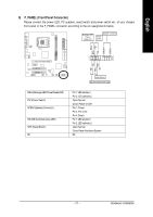
English 13) HDA_SUR (Surround Center Connector) To enable 7.1-channel audio, connect a 5.1/7.1 surround cable to this header and configure audio output mode via the audio software. For purchasing the optional 5.1/7.1 surround cable, please contact the local dealer. Pin No. Definition 2 14 1 LEF_P 2 SURR_RR 1 13 3 CEN_P 4 SURR_LL 5 CEN_JD 6 SURR_JD 7 GND 8 -SUR_DET 9 GND 10 No Pin 11 GND 12 S_SURR_JD 13 S_SURR_LL 14 S_SURR_RR 14) F_USB1 / F_USB2 (Front USB Connectors) The connectors conform to USB 2.0/1.1 specification. Each USB header can provide two USB ports via an optional USB bracket. For purchasing the optional USB bracket, please contact the local dealer. 2 10 1 9 Pin No. 1 2 3 4 5 6 7 8 9 10 Definition Power(5V) Power(5V) USB0 DXUSB1 DYUSB0 DX+ USB1 DY+ GND GND No Pin NC GA-VM900M Motherboard - 24 -
-
 1
1 -
2
-
3
-
4
-
5
-
6
-
7
-
8
-
9
-
10
-
11
-
12
-
13
-
14
-
15
-
16
-
17
-
18
-
 19
19 -
 20
20 -
 21
21 -
 22
22 -
 23
23 -
 24
24 -
 25
25 -
 26
26 -
 27
27 -
 28
28 -
 29
29 -
30
-
31
-
32
-
33
-
34
-
35
-
36
-
37
-
38
-
39
-
40
-
41
-
42
-
43
-
44
-
45
-
46
-
47
-
48
-
49
-
50
-
51
-
52
-
53
-
54
-
55
-
56
-
57
-
58
-
59
-
60
-
61
-
62
-
63
-
64
-
65
-
66
-
67
-
68
-
69
-
70
-
71
-
72
-
73
-
74
-
75
-
76
-
77
-
78
-
79
-
80
 |
 |
