Gigabyte GA-X79-UD7 User Manual - Page 23
Onboard Voltage Measurement Module
 |
View all Gigabyte GA-X79-UD7 manuals
Add to My Manuals
Save this manual to your list of manuals |
Page 23 highlights
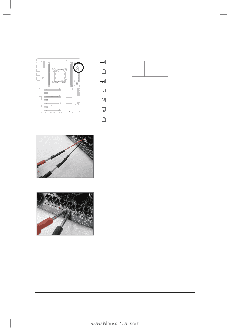
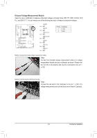
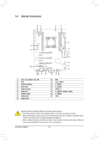
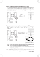
Onboard Voltage Measurement1 Module 1 23 Users can use a multimeter to measure component voltages, including Vcore, QPI VTT, DDR, VCCSA, CPU 1 PLL, and DDR VTT. You can employ one of the followiDnIP g two ways to measure component voltages. 1 23 Method I (Using the included voltage measurement cable): Steps: Connect the included voltage measurement cable to a voltage measurement header and your multimeter as shown. Please note the red wire is the positive and must be connected to the pin 1 (+12V). Method II (Connecting the multimeter directly): Steps: Connect the red lead of the multimeter to the pin 1 (+12V) of a voltage measurement point and the black lead to the pin 2 (ground). F_USB30 F_USB30 F_USB30 F_USB30 F_USB30F_AFU_DUISOB(3H0)F_AFU_UDSIOB(3H0)F_AUDIO(H)F_AUDIO(H)F_AUDIO(H)F_AUDIO(FH_)PFA_ANUEDL(INOH(FH)_)PANEL(NHF)_PANEL(NHF)_PANEL(NHF)_PANEL(NHF)_FP_APNAENLE(LNHF)_FP_APNAENLE(NLH)F_ (H61M-D2) (H61M-D2) (H - 23 - DIP 1 23 1 DIP 1 23 1 DIP 1 23 1 DIP 1 23 1 DIP 1 23 1 DIP 1 23 1 DIP 1 23 1 1 DIP 1 VCORE DIP 1 23 1 Pin 1 QPIVTT DIP 1 23 1 Pin 1 DDR_15V_DAIP 1 23 1 Pin 1 DDR_15V_B BIOS SwitcheBrIO(XS58SAw-iOtcChBe) rIO(XS5S8Aw-itOchCeB)rIO(XS58SAw-iOtcCheB) rIO(XS5S8Aw-iOtcChBe)rIO(XS5S8Aw-itOchCeB)rIO(XS5S8Aw-iOtcChe)r (X58A-OC) DB_PORT DB_PORT DB_PORT DB_PORT DB_PORT DB_PORT DB_PORT 1 1 1 1 1 1 1 1 1 1 1 1 1 1 M_SATA M_SATA M_SATA M_SATA M_SATA M_SATA M_SATA Pin 1 Pin 1 Pin 1 TPM w/housing TPM w/housing TPM w/housing TPM w/housing ACPI_CPT ACPI_CPT AC Voltage measVuorletamgeenmt meaosVduourletam(gXe5n8mtAme-aOosVdCuou)rleteam(gXee5n8mtAme-aOosVdCuuor)letam(gXe5n8mtAme-aOosVdCuou)rleteam(gXe5nm8tAme-aOosVdCuour)lleteam(gXe5nm8tAme-aOosdCuur)leem(Xe5n8tAm-OodCu)le(X58A-OC) (GA-IVB) (GA-IVB) (G TPM TPM TPM w/housing w/housing w/housing PWM SwitchP(XW5M8AS-OwiCtc)hP(WX5M8AS-wOiCtc)hP(XW5M8AS-OwiCtc)hP(XW5M8AS-wOiCtc)hP(WX5M8AS-wOiCtc)hP(XW5M8AS-wOiCtc)h (X58A-OC) DIP 1 23 DIP 1 23 DIP 1 23 DIP 1 23 DIP 1 23 DIP 1 23 DIP 1 23 VCCSA CPU_PLL Pin 1 DDRVTT DIP 1 23 DIP 1 23 DIP 1 23 DIP 1 23 DIP 1 23 DIP DIP 1 23 PCIe power cPoCnIneepctoowr e(Sr AcPoTCnAIne)(eXpc5oto8wrAe(-rSOcAPCoTCn)AIne)e(Xpc5too8wrAe(-SrOAcPCoTCnA)In)e(eXpc5oto8wrAe(-SrOcAPCoTCn)AIne)(eXpco5tow8rAe(-rSOcAPCoTCn)AIne)e(Xpcot5ow8rAe(Sr-OcAoCTnA)n)e(Xc5to8rA(-SOACT)A)(X58A-OC) 1 23 1 23 DIP DIP 1 2 3 SMB_CPT SMB_CPT SM (GA-IVB) (GA-IVB) (G Pin No. Definition 1 +12V 2 GND CLR_CMOS CLR_CMOSC CI CI CI DIS_ME DIS_ME DI GP15_CPT GP15_CPT G (GA-IVB) (GA-IVB) (G XDP_CPU XDP_CPU X XDP_PCH XDP_PCH X (GA-IVB) (GA-IVB) (G Hardware Installation
-
 1
1 -
2
-
3
-
4
-
5
-
6
-
7
-
8
-
9
-
10
-
11
-
12
-
13
-
14
-
15
-
16
-
17
-
 18
18 -
 19
19 -
 20
20 -
 21
21 -
 22
22 -
 23
23 -
 24
24 -
 25
25 -
 26
26 -
 27
27 -
 28
28 -
29
-
30
-
31
-
32
-
33
-
34
-
35
-
36
-
37
-
38
-
39
-
40
-
41
-
42
-
43
-
44
-
45
-
46
-
47
-
48
-
49
-
50
-
51
-
52
-
53
-
54
-
55
-
56
-
57
-
58
-
59
-
60
-
61
-
62
-
63
-
64
-
65
-
66
-
67
-
68
-
69
-
70
-
71
-
72
-
73
-
74
-
75
-
76
-
77
-
78
-
79
-
80
-
81
-
82
-
83
-
84
-
85
-
86
-
87
-
88
-
89
-
90
-
91
-
92
-
93
-
94
-
95
-
96
-
97
-
98
-
99
-
100
-
101
-
102
-
103
-
104
-
105
-
106
-
107
-
108
-
109
-
110
-
111
-
112
-
113
-
114
-
115
-
116
-
117
-
118
-
119
-
120
 |
 |