Haier DW9-CBE7 User Manual - Page 9
Assembly Instructions for Integrated Dishwasher
 |
View all Haier DW9-CBE7 manuals
Add to My Manuals
Save this manual to your list of manuals |
Page 9 highlights
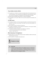
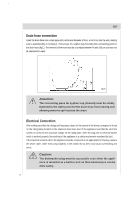
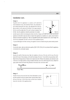
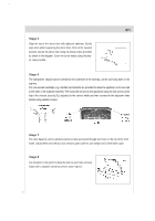
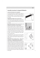
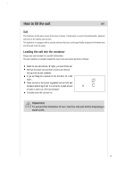
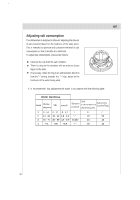
en Assembly Instructions for Integrated Dishwasher Technical Information for Installation The control panel (except in the completely built-in version) can be easily aligned with the kitchen drawers, using the spacers sup- plied with the appliance ( see Fig.1 and Fig.2).The height of the control panel is 115 mm, while the three spacers each add 7.5 mm in height. Adjusting the Height of the Control Panel If the kitchen decor requires that the height of the panel be modi- Fig.1 fied , it can be increased by adding spacers at the bottom of the control panel itself (see Fig.1 and Fig.2). Each spacer adds 7.5 mm in height. Mounting the Wooden Panel onto the Door and Sliding the Dishwasher into the Cabinet During the preparatory stages for installing the dishwasher into the kitchen cabinet, holes must not be drilled in the sides, or door, in order to avoid compromising the performance and/or operation of the appliance. Before working on any internal components, the Fig.2 unit must be disconnected from the power supply .The maximum dimensions for the wood panel that can be installed on the door are: Height - 725 mm for the completely built-in version; Width - 448 mm; Thickness-20 mm. A B The height dimension of 725 mm must be reduced if the height of the control panel is increased through the use of the spacers. In addition, the base must be trimmed if it interferes with the open- ing of the door. Using the Drilling Template (Fig.3 - totally builtFig.3 in and Fig.4 - integrated with control panel ) Align the top edge of the template (identified with the "A" arrow ) with the top edge of the panel. On both sides of the template (top and bottom ) are written the various dimensions that correspond to the different possible widths for the panel. Align the template with the side of the panel (left or right), making sure that the panel coincides with the appropriate dimensions. Mark the positions for the holes for the screws, using the tip of a drill or a pencil. The three holes closest to the side should be used(B). Repeat this step on the other side of the panel ,using the corresponding side mm 115 122.5 130 137.5 145 152.5 582mm 586mm 590mm 594mm LARGH.=598mm LARGH.=598mm 594mm 590mm 586mm 582mm A mm111522.15310371.541552.5 5825m8m65Lm9A0m5mR9Gm4mHm.=598mm mm111522.15310371.541552.5 B 5825m8m65Lm9A0m5mR9Gm4mHm.=598mm LARGH.=5599458m9m0m5mm86m5m82mmm LARGH.=5599458m9m0m5mm86m5m82mmm Fig.4 of the template. 8
-
 1
1 -
2
-
3
-
 4
4 -
 5
5 -
 6
6 -
 7
7 -
 8
8 -
 9
9 -
 10
10 -
 11
11 -
 12
12 -
 13
13 -
 14
14 -
15
-
16
-
17
-
18
-
19
-
20
-
21
-
22
-
23
-
24
-
25
-
26
-
27
-
28
-
29
-
30
-
31
-
32
-
33
-
34
-
35
 |
 |
