Haier HB4800VA1M25 User Manual
Haier HB4800VA1M25 Manual
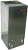 |
View all Haier HB4800VA1M25 manuals
Add to My Manuals
Save this manual to your list of manuals |
Haier HB4800VA1M25 manual content summary:
- Haier HB4800VA1M25 | User Manual - Page 1
Manual Air Handler 10 to 12 SEER 3 to 5 Tons Models: HB3600VC1M25 HB4200VA1M25 HB4800VA1M25 HB6000VA1M25 HB6000VC1M25 WARNING WHEN THIS APPLIANCE 90B UNIFORM MECHANICAL CODE READ THESE INSTRUCTIONS COMPLETELY BEFORE ATTEMPTING TO INSTALL OR SERVICE THIS APPLIANCE. ONLY FACTORY AUTHORIZED KITS OR - Haier HB4800VA1M25 | User Manual - Page 2
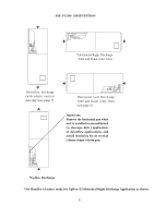
Air Flow Orientation Horizontal Left-Hand Instructions Downflow Instructions Refrigerant Tubing Condensate Removal Electrical Connections Thermostat Wiring Orifice Change Circulating Air 70 Uniform Mechanical Code Prior to shipment, this appliance was tested and inspected for damage at the factory - Haier HB4800VA1M25 | User Manual - Page 3
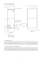
PHYSICAL DIMENSIONS D 0.8" C [2.1cm] PLASTIC BREAKER COVER B E 12.2" [31 cm] 5.1" [13 cm] F K G 2.4" [ 6 cm] 1.2" [ 3 cm] H INLET FRONT VIEW PRIMARY & SECONDARY CONDENSATE DRAINSHORIZONTAL 3/4" NPT 2" [5.08 cm] 1.1" [2.9 cm] 2" SUCTION LINE [5.08 cm] TYPICAL LIQUID LINE 5" [12.7 cm - Haier HB4800VA1M25 | User Manual - Page 4
appliance can be installed in the vertical or right horizontal position without modification. The horizontal left and downflow positions require product modification. This product is designed for zero inch (0") clearance; however, adequate access for service This secondary drain pan is required in the - Haier HB4800VA1M25 | User Manual - Page 5
. front (see page 6) Important: Remove the horizontal pan when unit is installed in unconditioned i.e. (Garage, Attic ) application, or downflow applications, and install insulation kit on vertical ( donut shape ) drain pan. *Upflow Discharge *Air Handler is factory ready for Upflow & Horizontal - Haier HB4800VA1M25 | User Manual - Page 6
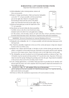
INSTRUCTIONS Important: Read instructions below carefully. 1) With Airhandler in the vertical position, remove all three access panels. 2) Remove J-shape metal bracket. Slide out from the Airhandler cavity the "A" coil pan assembly with horizontal drain pan 150 p.s.i.g. of air pressure. Before - Haier HB4800VA1M25 | User Manual - Page 7
IN THIS DOWNFLOW APPLICATION Fig.1 Fig.2 TOP OF WRAPPER INSULATION JACKET ZEE COIL SUPPORT WRAPPER STIFFENER DRAIN PAN INSULATION DPI KIT (HATCHED AREA) BLOWER MOTOR WARNING: The "A" coil contains 150 p.s.i.g. of air pressure Before setting up flowrator assembly for field brazing see page 12 or - Haier HB4800VA1M25 | User Manual - Page 8
REFRIGERANT TUBING Refrigerant tubing should be installed as to avoid undue stress. They must be supported the air handler. Do not reduce the recommended tubing size. CONDENSATE REMOVAL THIS APPLIANCE EMPLOYS to prevent damage to the plastic drain pan during the soldering process. All condensate - Haier HB4800VA1M25 | User Manual - Page 9
wiring diagram on the air handler. All pertinent information, such as the rating Ampacity Over-current Motor 208/230 208/230 FLA HB4200VA1M25 -------- 15/15 2.2 Blower Motor H.P. 1/2 HB4800VA1M25 RELIEF MUST BE INSTALLED TO THIS APPLIANCE AT THE ELECTRICAL SERVICE ENTRANCE. When an optional electric - Haier HB4800VA1M25 | User Manual - Page 10
SWITCH MODE SWITCH Open for heating Close for cooling control the indoor unit & heat pump outdoor unit at the same time no air supply mode. If need select the air supply mode, switch can adopt multi-connect switch or select switch. The detailed infor see the following diagram TO INDOOR FAN RELAY - Haier HB4800VA1M25 | User Manual - Page 11
different power switch show diagram 5. This mode is control the indoor unit & cooling only outdoor unit at the same time no air supply mode. If need select the air supply mode, switch can adopt multi-connect switch or select switch. The detailed infor see the following diagram 6. TO FAN RELAY - Haier HB4800VA1M25 | User Manual - Page 12
piston to verify it is correct. See piston kit chart in instructions. 4) Use a tube cutter to remove the spin closure on Manual "K". The use of flexible duct connectors is recommended to minimize the possibility of noise transmission. These connectors must conform to U.L. standards. Supply air - Haier HB4800VA1M25 | User Manual - Page 13
coil w/ filter) 4% reduction for wet coil. Static Pressure Model HB4200VA1M25 HB4800VA1M25 CFM High Middle HB6000VA1M25 0.15 1449 1449 0.2 0.25 0.3 1244 1213 1184 1157 1127 1097 2063 2008 1953 1898 1841 1784 The air delivery can be varied by changing the blower speeds. This can allow for - Haier HB4800VA1M25 | User Manual - Page 14
necessary, and pitched to allow for drainage. Drain pans and drain tubing were leak checked with water. Retrun protected from vehicular or other physical damage. Return air is not to be obtained from any areas where POWER SUPPLIES BEFORE PERFORMING ANY SERVICE. The only item to be maintained on - Haier HB4800VA1M25 | User Manual - Page 15
-
 1
1 -
 2
2 -
 3
3 -
 4
4 -
 5
5 -
 6
6 -
 7
7 -
8
-
9
-
10
-
11
-
12
-
13
-
14
-
15
 |
 |
10 to 12 SEER
3 to 5 Tons
HB3600VC1M25
HB4200VA1M25
Installation & Operation Manual
Air Handler
HB6000VA1M25
HB6000VC1M25
HB4800VA1M25
WARNING
WHEN THIS APPLIANCE IS INSTALLED IN AN ENCLOSED AREA, SUCH AS
A GARAGE OR UTILITY ROOM, WITH ANY CARBON MONOXIDE PRODUCING
DEVICES (i.e. AUTOMOBILE, SPACE HEATER, WATER HEATER,ETC.) INSURE
THAT THE ENCLOSED AREA IS PROPERLY VENTILATED.
WARNING
CARBON MONOXIDE (REFERED TO AS CO) CAN CAUSE PERSONAL INJURY
OR DEATH
WARNING
FAILURE TO FOLLOW THESE INSTRUCTIONS, LOCAL CODES OR NATIONAL
CODES MAY CAUSE FIRE, EXPLOSION, ELECTRICAL SHOCK, PERSONAL
INJURY OR PROPERTY DAMAGE.
FOLLOW ALL LOCAL CODES. IN THE ABSENCE OF LOCAL CODES REFER TO :
NATIONAL ELECTRICAL CODE NFPA 70
NFPA 90A & 90B
UNIFORM MECHANICAL CODE
READ THESE INSTRUCTIONS COMPLETELY BEFORE ATTEMPTING TO INSTALL
OR SERVICE THIS APPLIANCE.
ONLY FACTORY AUTHORIZED KITS OR ACCESSORIES SHOULD BE USED WHEN
INSTALLING OR MODIFYING THIS APPLIANCE, UNLESS OTHERWISE NOTED IN
THESE INSTRUCTIONS.
SOME LOCALITIES MAY REQUIRE THE INSTALLER/SERVICER TO BE LICENSED.
IF IN DOUBT CONTACT YOUR LOCAL AUTHORITIES.
These instructions should be retained and kept adjacent to the unit for future reference.
MODEL #
HB
00VA1M25
MODEL #
HB
00VC1M25
INSTALLATION DATE
The information contained in this booklet is subject to change without notice.
No. 0010575351
E
Models: