Haier HB4800VA1M25 User Manual - Page 10
Thermostat Wiring
 |
View all Haier HB4800VA1M25 manuals
Add to My Manuals
Save this manual to your list of manuals |
Page 10 highlights
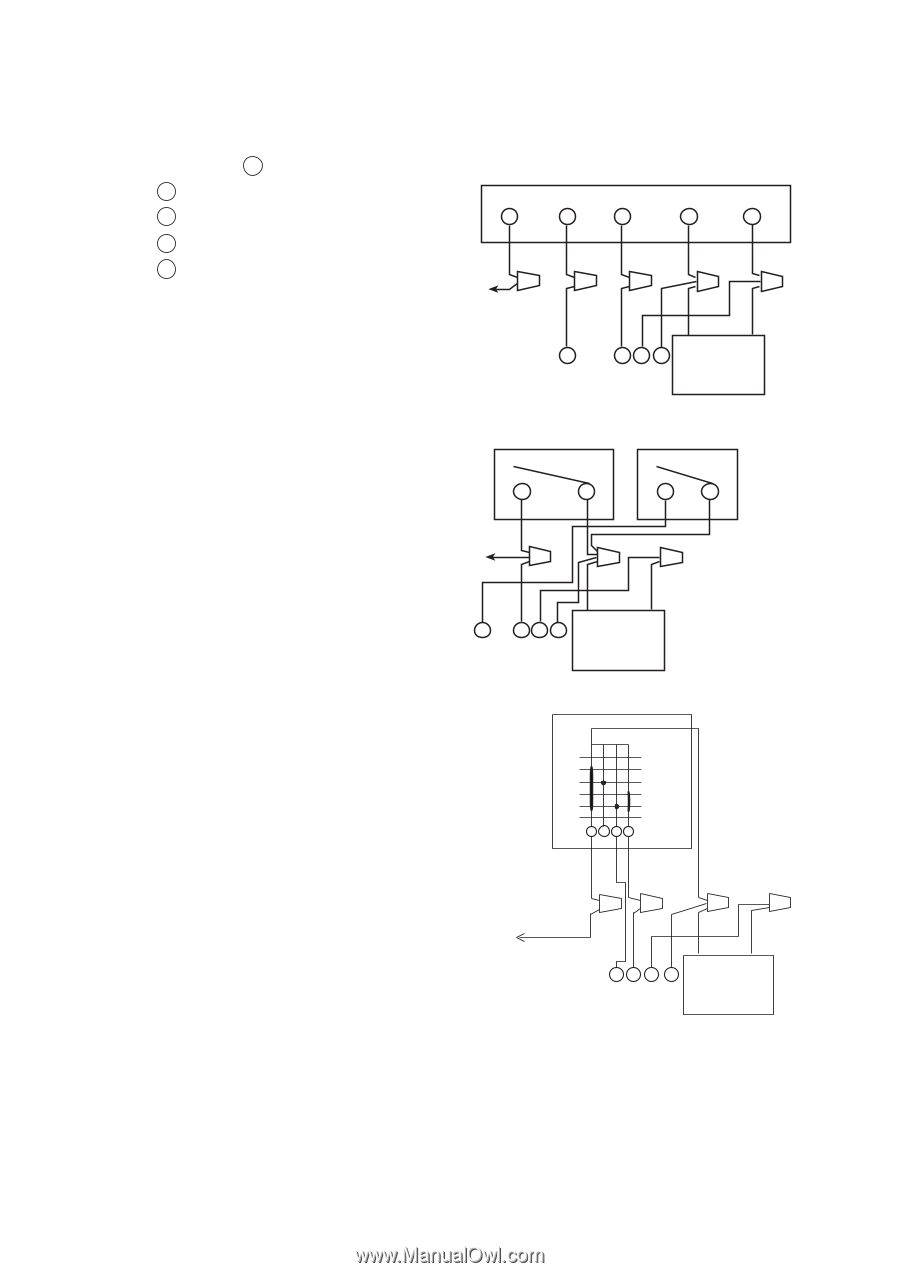
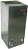
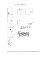
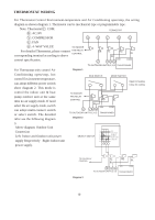
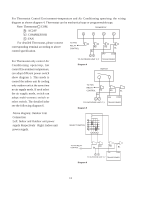
THERMOSTAT WIRING For Thermostat Control Environment-temperature and Air Conditioning open/stop, the wiring diagram as shown diagram 1. Thermostat can be mechanical type or programmable type. Note: Thermostat C : COM. R : AC24V TERMOSTAT Y : COMPRESSOR G O Y R C G : FAN O : 4 -WAY VALUE TO INDOOR For detailed Thermostat, please connect FAN RELAY CONTROL corresponding terminal according to above control specification. OR YL RD BL BL 24V COM O YCR TO OUTDOOR UNIT R,C,Y,O TRANSFORMER For Thermostat only control Air Diagram 1 Conditioning open/stop, hot control Environment temperature, can adopt different power switch show diagram 2. This mode is RUN SWITCH MODE SWITCH Open for heating Close for cooling control the indoor unit & heat pump outdoor unit at the same time no air supply mode. If need select the air supply mode, switch can adopt multi-connect switch or select switch. The detailed infor see the following diagram TO INDOOR FAN RELAY CONTROL RD RD BL BL 24V O YCR COM TO OUTDOOR UNIT R,C,Y,O TRANSFORMER Diagram 2 3. Above diagram: Outdoor Unit Connection Left: Indoor and Outdoor unit power supply Respectively Right: Indoor unit power supply. 1 2 SELECT SWITCH 3 4 5 6 OFF FAN ONLY E. HEAT HEAT PUMP COOLING TO FAN RELAY CONTROL YL RD BL BL OY C R TO OUTDOOR UNIT R,C,Y,O 24V COM TRANSFORMER Diagram 3 10
-
 1
1 -
2
-
3
-
4
-
 5
5 -
 6
6 -
 7
7 -
 8
8 -
 9
9 -
 10
10 -
 11
11 -
 12
12 -
 13
13 -
 14
14 -
 15
15
 |
 |