Haier HB4800VA1M25 User Manual - Page 11
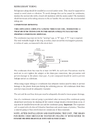
For Thermostat Control Environment-temperature and Air Conditioning open/stop, the wiring
 |
View all Haier HB4800VA1M25 manuals
Add to My Manuals
Save this manual to your list of manuals |
Page 11 highlights
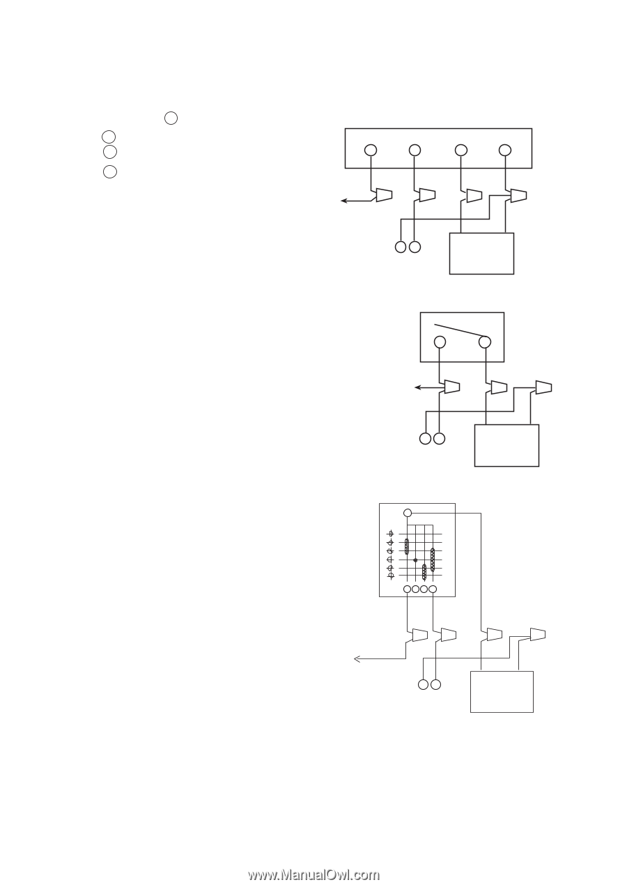
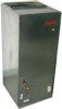
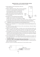
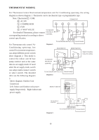
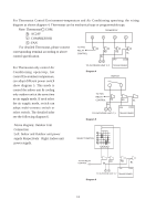
For Thermostat Control Environment-temperature and Air Conditioning open/stop, the wiring diagram as shown diagram 4. Thermostat can be mechanical type or programmable type. Note: Thermostat C: COM. R : AC24V TERMOSTAT Y : COMPRESSOR G Y R C G : FAN For detailed Thermostat, please connect corresponding terminal according to above control specification. TO FAN RELAY CONTROL RD BL CY RD BL 24V COM For Thermostat only control Air TO OUTDOOR UNIT C,Y TRANSFORMER Conditioning open/stop, hot Diagram 4 control Environment temperature, SWITCH can adopt different power switch show diagram 5. This mode is control the indoor unit & cooling only outdoor unit at the same time no air supply mode. If need select the air supply mode, switch can adopt multi-connect switch or select switch. The detailed infor see the following diagram 6. TO FAN RELAY CONTROL RD BL CY TO OUTDOOR UNIT C,Y RD BL 24V COM TRANSFORMER Diagram 5 Above diagram: Outdoor Unit Connection Left: Indoor and Outdoor unit power supply Respectively Right: Indoor unit power supply. 1 2 SELECT SWITCH 3 4 5 6 TO FAN RELAY CONTROL RD BL RD BL CY 24V COM TO OUTDOOR UNIT C,Y TRANSFORMER Diagram 6 11
-
 1
1 -
2
-
3
-
4
-
5
-
 6
6 -
 7
7 -
 8
8 -
 9
9 -
 10
10 -
 11
11 -
 12
12 -
 13
13 -
 14
14 -
 15
15
 |
 |