Haier HB4800VA1M25 User Manual - Page 9
Electrical Connections, Warning, Without
 |
View all Haier HB4800VA1M25 manuals
Add to My Manuals
Save this manual to your list of manuals |
Page 9 highlights
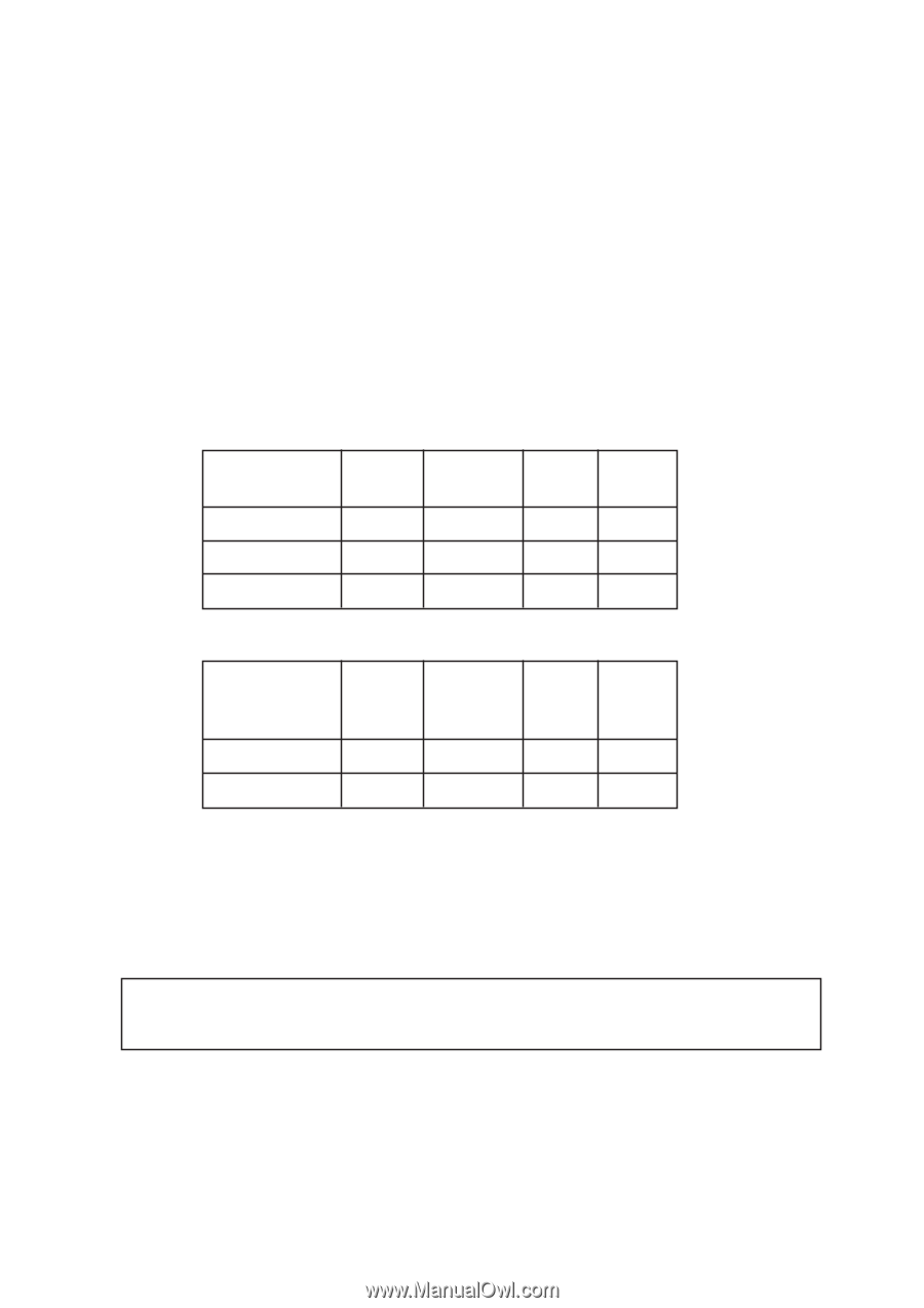
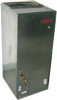
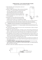
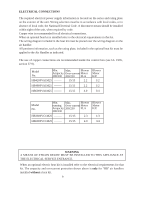
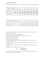
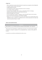
ELECTRICAL CONNECTIONS The required electrical power supply information is located on the series and rating plate on the exterior of the unit. Wiring selection must be in accordance with local codes, or in absence of local code, the National Electrical Code. A disconnect means should be installed within sight of the unit, when required by code. Copper wire is recommended for all electrical connections. When an optional heat kit is installed refer to the electrical requirements in that kit. The wiring diagram included in the heat kit must be placed over the wiring diagram on the air handler. All pertinent information, such as the rating plate, included in the optional heat kit must be applied to the Air Handler as indicated. The use of copper connections are recommended inside the control box (see UL 1995, section 37.9). Model No. Min. Max. Blower Ampacity Over-current Motor 208/230 208/230 FLA HB4200VA1M25 -------- 15/15 2.2 Blower Motor H.P. 1/2 HB4800VA1M25 -------- 15/15 2.2 1/2 HB6000VA1M25 -------- 15/15 4.0 3/4 Model No. Min. Max. Blower running Over-current Motor Ampacity 208/230 FLA 208/230 HB3600VC1M25 -------- 15/15 2.3 Blower Motor H.P. 1/3 HB6000VC1M25 -------- 15/15 4.0 3/4 WARNING A MEANS OF STRAIN RELIEF MUST BE INSTALLED TO THIS APPLIANCE AT THE ELECTRICAL SERVICE ENTRANCE. When an optional electric heat kit is installed refer to the electrical requirements for that kit. The ampacity and overcurrent protection shown above is only for "HB" air handlers installed without a heat kit. 9
-
 1
1 -
2
-
3
-
 4
4 -
 5
5 -
 6
6 -
 7
7 -
 8
8 -
 9
9 -
 10
10 -
 11
11 -
 12
12 -
 13
13 -
 14
14 -
15
 |
 |