Harman Kardon AVR30 Owners Manual - Page 8
Connecting, Audio, Components, installation, connections, diagram, details, Antenna, Installation,
 |
View all Harman Kardon AVR30 manuals
Add to My Manuals
Save this manual to your list of manuals |
Page 8 highlights
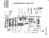
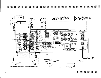
Connecting Audio Components (see the installation and connections diagram on page 4 for details) 1. Make sure the AVR30 and other components are turned off. 2. Connect each component's Output jacks to the corresponding "In" jacks on the back of your receiver. Use the white, black or gray plugs to connect Left channel jacks; use the red plugs for Right jacks. Connect your turntable to the jacks marked "Phono". Also connect the ground wire from the turntable to the terminal marked "GND" next to the Phono jacks. Antenna Installation Select the FM antenna that best meets your needs. 1. An indoor dipole antenna is supplied with your AVR30. This will work well if you are located in a strong signal area. 2. Other indoor antennas are available which may improve reception by offering greater positioning flexibility. 3. If reception is unsatisfactory using indoor antennas, an outdoor antenna should be installed. 4. Alternatively, you may connect to an FM cable antenna, if available. Connect the FM antenna. Connect the two leads of the antenna to the two screw-down terminals marked "FM 30052BAL". If you wish to connect a cable antenna, connect it to the location marked "FM 7552 UNBAL" (see antenna connection diagram for details). Position the FM antenna for optimum reception. Reception from all of the above antennas (except the cable antenna) may be improved by re-positioning them. Try your antenna in different positions to find the one in which most of your desired broadcast stations have high signal strength readings and good sound quality. Connect the AM Antenna. Your receiver comes with an AM loop antenna which provides good reception in most locations. For best results, place this antenna away from the unit and away from contact with any metal object. In areas where AM signals are weak, an outdoor AM antenna may improve sound quality. Connect the AM antenna leads to the screw-down terminals marked "AM" on the back of the AVR30 (see antenna connection diagram for details). SPEAKER INSTALLATION This unit is designed to work with 6 to 16 ohm impedance speakers in the front and 4 to 16 ohm speakers in the rear. For best performance, use high quality speaker cables. However, ordinary copper wire can be used if the gauge meets the following requirements: Wire Lenth Up to 8 feet Up to 12 feet Up to 20 feet Over 20 feet Gauge 18 AWG 16 AWG 14 AWG 10-12 AWG custom speaker cable NOTE: Avoid coiling excess wire with or near line level hook-up cords. Connect the first pair of front speakers to receiver terminals marked "Speaker System" "A". 7
-
 1
1 -
2
-
 3
3 -
 4
4 -
 5
5 -
 6
6 -
 7
7 -
 8
8 -
 9
9 -
 10
10 -
 11
11 -
 12
12 -
 13
13 -
14
-
15
-
16
-
17
-
18
-
19
-
20
-
21
-
22
 |
 |
