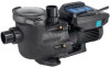
Hayward TriStar VS 950 2.70 THP VS Pump Family - Owners Manual - Page 23
Attention, Warning
 |
View all Hayward TriStar VS 950 manuals
Add to My Manuals
Save this manual to your list of manuals |
Page 23 highlights
! ATTENTION - Allowing the pump to freeze with water in it will void the warranty. ! ATTENTION - Use ONLY propylene glycol as antifreeze in your pool/spa system. Propylene glycol is nontoxic and will not damage plastic system components; other anti-freezes are highly toxic and may damage plastic components in the system. Drain all water from pump and piping when expecting freezing temperatures or when storing pump for a long time (see instructions below). Gravity drain system as far as possible. Keep motor dry and covered during storage. To avoid condensation/corrosion problems, do NOT cover or wrap pump with plastic film or bags. Storing Pump for Winterization ! WARNING - To avoid dangerous or fatal electrical shock hazard, turn OFF power to motor before draining pump. Failure to disconnect power may result in serious personal injury or death. 1. Drain water level below all inlets to the pool. 2. Remove drain plugs and strainer cover from strainer housing (see parts diagram on page 23 for pump component locations). 3. Disconnect pump from mounting pad, wiring (after power has been turned OFF), and piping. 4. Once the pump is fully drained of water, re-install the strainer cover and drain plugs. Store pump in a dry area. Shaft Seal Change Instructions When servicing electrical equipment, basic safety precautions should always be observed including the following. Failure to follow instructions may result in injury. ! WARNING - To reduce risk of injury, do not permit children to use this product. • Disconnect all electrical power service to pump before beginning shaft seal replacement. • Only qualified personnel should attempt rotary seal replacement. Contact your local authorized Hayward Dealer or service center if you have any questions. • Refer to page 23 for pump component locations. Exercise extreme care in handling both the rotating and the stationary sections of the two-part replacement seal. Foreign matter or improper handling will easily scratch the graphite and ceramic sealing surfaces. Removing the Motor Assembly 1. Remove the six (6) 5/16" x 2" hex head bolts (item #17), which hold the motor assembly to the pump/strainer housing (item #3), using a 1/2" wrench or socket. 2. Slide the motor assembly out of the pump/strainer housing (item #3), exposing the diffuser (item #9). Remove the two diffuser screws (item #7), and pull the diffuser (item #9) off of the seal plate (item #15) to expose the impeller (item #12). Removing the Impeller 3. To prevent the motor shaft from turning, secure using a 5/16" hex wrench in the socket on the motor shaft. 4. Rotate the impeller screw (item #10) clockwise (note that screw has left-hand thread) and remove. Remove the impeller (item #12) by rotating counter- clockwise. Removing the Ceramic Seat 5. Remove the spring seal assembly (item #13) and seal plate (item #15) from the motor by removing the four (4) 3/8" x 1" bolts (item #18) that secure it to the motor, using a 9/16" wrench or socket. Remove the motor support bracket (item #20) from the seal plate (item #15). 6. Press the ceramic seat with rubber cup out of the seal plate (item #15). Use a small screwdriver to tap seal out. STOP - Clean all recesses & parts to be reassembled. Inspect gaskets & replace if necessary. Seal Installation 7. Clean and lightly lubricate the motor shaft and seal recesses in the seal plate (item #15) with a dilute solution of non-granulated liquid-type soap. Gently wipe the polished face of the ceramic seal with a soft cotton cloth. Lubricate the rubber cup on the ceramic seat and press it firmly into the recess of the seal plate (item #15), with the polished ceramic surface facing out. 8. Reassemble the motor to the seal plate (item #15) using the four (4) 3/8" x 1" bolts (item #18), and re-attach the motor support (item #20) to the seal plate (item #15). Ensure that the upper two housing bolts are installed in the seal plate prior to mounting the motor to the seal plate. 22 USE ONLY HAYWARD GENUINE REPLACEMENT PARTS
-
 1
1 -
2
-
3
-
4
-
5
-
6
-
7
-
8
-
9
-
10
-
11
-
12
-
13
-
14
-
15
-
16
-
17
-
 18
18 -
 19
19 -
 20
20 -
 21
21 -
 22
22 -
 23
23 -
 24
24 -
 25
25 -
 26
26 -
 27
27 -
 28
28
 |
 |
