Hayward TriStar VS TriStar VS Manual - Page 15
Wiring Diagrams
 |
View all Hayward TriStar VS manuals
Add to My Manuals
Save this manual to your list of manuals |
Page 15 highlights
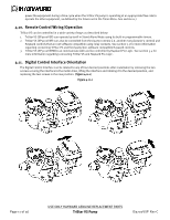
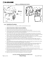
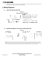
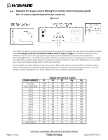
16. Apply power to the system, and proceed to "Configuration Menu", section 6.6 (SP3200VSP only), or see section 5.4 for details regarding Pro Logic control of SP3200VSPND. 5. Wiring Diagrams 5.1. Input Power Wiring (Required) Figure 5.1-1 DRIVE HIGH VOLTAGE CONNECTIONS 5.2. Wall Mounted Digital Control Interface Wiring (Optional) Figure 5.2-1 Note: Connection wire must be rated for a minimum of 300V, and may be up to 500 feet in length. Use removable 4-position terminal block connectors for wiring connection to interface and motor drive PCB's taking care to note the wire colors and corresponding numbers next to the connectors. SW200 DIP switch #1 and #2 must be "ON". Page 15 of 36 USE ONLY HAYWARD GENUINE REPLACEMENT PARTS TriStar VS Pump IS3200VSP Rev-C
-
 1
1 -
2
-
3
-
4
-
5
-
6
-
7
-
8
-
9
-
 10
10 -
 11
11 -
 12
12 -
 13
13 -
 14
14 -
 15
15 -
 16
16 -
 17
17 -
 18
18 -
 19
19 -
 20
20 -
21
-
22
-
23
-
24
-
25
-
26
-
27
-
28
-
29
-
30
-
31
-
32
-
33
-
34
-
35
-
36
 |
 |
