Hayward TriStar VS TriStar VS Manual - Page 28
Replacement Parts
 |
View all Hayward TriStar VS manuals
Add to My Manuals
Save this manual to your list of manuals |
Page 28 highlights
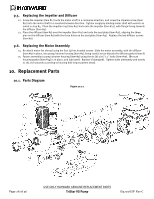
9.5. Replacing the Impeller and Diffuser 12. Screw the impeller (item #12) onto the motor shaft in a clockwise direction, and screw the impeller screw (item #10) into the motor shaft in a counterclockwise direction. Tighten snugly by holding motor shaft with wrench as noted in step #4. Place the impeller ring (item #11) back onto the impeller (item #12), with flange facing towards the diffuser (item #9). 13. Place the diffuser (item #9) over the impeller (item #12) and onto the seal plate (item #15), aligning the three pins on the diffuser (item #9) with the three holes on the seal plate (item #15). Replace the two diffuser screws (item #7). 9.6. Replacing the Motor Assembly 14. Re-attach motor fan shroud using the four (4) hex headed screws. Slide the motor assembly, with the diffuser (item #9) in place, into pump/strainer housing (item #3), being careful not to disturb the diffuser gasket (item 8) 15. Fasten assembly to pump/strainer housing (item #3) using the six (6) 5/16" x 2" bolts (item #17). (Be sure housing gasket (item #14) is in place, and lubricated. Replace if damaged). Tighten bolts alternately and evenly to 185 inch-pounds according to housing bolt torque pattern detail. 10. Replacement Parts 10.1. Parts Diagram Figure 10.1-1 Page 28 of 36 USE ONLY HAYWARD GENUINE REPLACEMENT PARTS TriStar VS Pump IS3200VSP Rev-C
-
 1
1 -
2
-
3
-
4
-
5
-
6
-
7
-
8
-
9
-
10
-
11
-
12
-
13
-
14
-
15
-
16
-
17
-
18
-
19
-
20
-
21
-
22
-
 23
23 -
 24
24 -
 25
25 -
 26
26 -
 27
27 -
 28
28 -
 29
29 -
 30
30 -
 31
31 -
 32
32 -
 33
33 -
34
-
35
-
36
 |
 |
