HP 3PAR StoreServ 7450 4-node HP 3PAR StoreServ 7450 Storage Service Guide - Page 18
Controller Node Replacement Procedure, Preparation
 |
View all HP 3PAR StoreServ 7450 4-node manuals
Add to My Manuals
Save this manual to your list of manuals |
Page 18 highlights
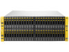
Figure 17 M6710 (2U24) Displayed as DCS2 in Software Output Figure 18 M6720 (4U24) Displayed as DCS1 in Software Output Controller Node Replacement Procedure When the failure notification is received customers should contact their Authorized Service Providers (ASPs) for assistance with failure verification, identification of the exact component to be replaced, and the location of the failed node, if replacement is required. NOTE: Do not order a replacement node until the ASP has verified the failure, including a procedure to reset the node. CAUTION: Alloy gray-colored latches on components like the node means that the component is warm-swappable. HP recommends that the node be shutdown (with the power remaining on) before removing this component. Contact your ASP for node diagnosis and shutdown. CAUTION: To prevent overheating, node replacement requires a maximum service time of 30 minutes. NOTE: Be sure to put on your electrostatic discharge wrist strap to avoid damaging any circuitry. Preparation When the replacement part has been received, complete the following steps before contacting your ASP for assistance with preparation for replacement: 1. Unpack the replacement node and place it on an ESD safe mat. 2. Remove the node cover: a. Loosen the two thumbscrews that secure the node cover to the node. b. Lift the node cover and remove. 3. If a PCIe adapter exists in the failed node: 18 Servicing the Storage System
-
 1
1 -
2
-
3
-
4
-
5
-
6
-
7
-
8
-
9
-
10
-
11
-
12
-
 13
13 -
 14
14 -
 15
15 -
 16
16 -
 17
17 -
 18
18 -
 19
19 -
 20
20 -
 21
21 -
 22
22 -
 23
23 -
24
-
25
-
26
-
27
-
28
-
29
-
30
-
31
-
32
-
33
-
34
-
35
-
36
-
37
-
38
-
39
-
40
-
41
-
42
-
43
-
44
-
45
-
46
-
47
-
48
-
49
-
50
-
51
-
52
-
53
-
54
-
55
-
56
-
57
-
58
-
59
-
60
-
61
-
62
-
63
-
64
-
65
-
66
 |
 |
