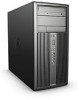
HP 6080 Maintenance & Service Guide: HP Compaq 6000 and 6080 Pro Business
HP 6080 - Pro Microtower PC Manual
 |
View all HP 6080 manuals
Add to My Manuals
Save this manual to your list of manuals |
HP 6080 manual content summary:
- HP 6080 | Maintenance & Service Guide: HP Compaq 6000 and 6080 Pro Business - Page 1
Maintenance & Service Guide HP Compaq 6000 and 6080 Pro Business PC - HP 6080 | Maintenance & Service Guide: HP Compaq 6000 and 6080 Pro Business - Page 2
document may be photocopied, reproduced, or translated to another language without the prior written consent of Hewlett-Packard Company. Maintenance & Service Guide HP Compaq 6000 and 6080 Pro Business PC Second Edition (March 2010) First Edition (September 2009) Document Part Number: 581650-002 - HP 6080 | Maintenance & Service Guide: HP Compaq 6000 and 6080 Pro Business - Page 3
About This Book WARNING! Text set off in this manner indicates that failure to follow directions could result in bodily harm or loss of life. CAUTION: Text set off in this manner indicates that failure to follow directions could result in damage to equipment or loss of information. NOTE: Text set - HP 6080 | Maintenance & Service Guide: HP Compaq 6000 and 6080 Pro Business - Page 4
iv About This Book - HP 6080 | Maintenance & Service Guide: HP Compaq 6000 and 6080 Pro Business - Page 5
Components ...7 Serial Number Location ...8 2 Installing and Customizing the Software ...9 Installing the Operating System ...9 Downloading Microsoft Windows Updates 10 Installing or Upgrading Device Drivers (Windows systems 10 Accessing Disk Image (ISO) Files ...10 Protecting the Software ...11 - HP 6080 | Maintenance & Service Guide: HP Compaq 6000 and 6080 Pro Business - Page 6
Saving and Printing Information in HP Vision Diagnostics 32 Downloading the Latest Version of HP Vision Diagnostics 32 Protecting the ) ...38 6000 model ...38 6080 model - Front Bezel 38 Electrostatic the Keyboard ...42 Cleaning the Monitor ...43 Cleaning the Mouse ...43 Service Considerations - HP 6080 | Maintenance & Service Guide: HP Compaq 6000 and 6080 Pro Business - Page 7
Holder ...87 Type 3 Battery Holder ...88 External Security Devices ...89 Cable Lock ...89 Padlock ...89 HP Business PC Security Lock 90 Front Bezel Security ...91 8 Removal and Replacement Procedures Small Form Factor (SFF) Chassis 93 Preparation for Disassembly ...93 Access Panel ...94 Front - HP 6080 | Maintenance & Service Guide: HP Compaq 6000 and 6080 Pro Business - Page 8
External Drive Bay 118 Removing and Replacing the Primary 3.5-inch Internal SATA Hard Drive 120 Removing and Replacing a Removable 3.5-inch SATA Hard Drive 140 Installing a Security Lock 140 Cable Lock ...140 Padlock ...141 HP Business PC Security Lock 141 Front Bezel Security 143 Using the - HP 6080 | Maintenance & Service Guide: HP Compaq 6000 and 6080 Pro Business - Page 9
Support 167 Helpful Hints ...168 Solving General Problems ...170 Solving Power Problems ...174 Solving Hard Drive Problems ...175 Solving Media Card Reader Problems 178 Solving Display Problems ...179 Solving Audio Problems ...183 Solving Printer Problems ...186 Solving Keyboard and Mouse Problems - HP 6080 | Maintenance & Service Guide: HP Compaq 6000 and 6080 Pro Business - Page 10
Appendix E Password Security and Resetting CMOS 204 Resetting the Password Jumper ...205 Clearing and Resetting the CMOS 206 Appendix F Specifications ...208 Microtower Chassis ...208 Small Form Factor Chassis ...210 Index ...212 x - HP 6080 | Maintenance & Service Guide: HP Compaq 6000 and 6080 Pro Business - Page 11
The HP Compaq Microtower features may vary depending on the model. For a complete listing of the hardware and software installed in the computer, run the diagnostic utility (included on some computer models only). Instructions for using the utility are provided in the Troubleshooting Guide. Figure - HP 6080 | Maintenance & Service Guide: HP Compaq 6000 and 6080 Pro Business - Page 12
: The Power On Light is normally green when the power is on. If it is flashing red, there is a problem with the computer and it is displaying a diagnostic code. Refer to the Troubleshooting Guide to interpret the code. 1 Some models have bezel blanks covering one or both of the 5.25-inch drive bays - HP 6080 | Maintenance & Service Guide: HP Compaq 6000 and 6080 Pro Business - Page 13
for powered audio devices (green) 7 PS/2 Keyboard Connector (purple) 3 PS/2 Mouse Connector (green) 8 VGA Monitor Connector 4 Serial Connector 5 RJ-45 Network For information about setting the boot VGA controller, refer to the Computer Setup (F10) Utility Guide. Microtower Chassis 3 - HP 6080 | Maintenance & Service Guide: HP Compaq 6000 and 6080 Pro Business - Page 14
Serial Number Location Each computer has a unique serial number and product ID number that are located on the top cover of the computer. Keep these numbers available for use when contacting customer service for assistance. Figure 1-2 Serial Number and Product ID Location 4 Chapter 1 Product Features - HP 6080 | Maintenance & Service Guide: HP Compaq 6000 and 6080 Pro Business - Page 15
The HP Compaq Small Form Factor features may vary depending on the model. For a complete listing of the hardware and software installed in the computer, run the diagnostic utility (included on some computer models only). Instructions for using the utility are provided in the Troubleshooting Guide - HP 6080 | Maintenance & Service Guide: HP Compaq 6000 and 6080 Pro Business - Page 16
The Power On Light is normally green when the power is on. If it is flashing red, there is a problem with the computer and it is displaying a diagnostic code. Refer to the Troubleshooting Guide to interpret the code. 1 Some models are configured with a 5.25-inch bezel blank covering this bay. 2 Some - HP 6080 | Maintenance & Service Guide: HP Compaq 6000 and 6080 Pro Business - Page 17
Mouse Connector (green) 7 VGA Monitor Connector 8 PS/2 Keyboard Connector (purple) 4 Power second serial port and an optional parallel port are available from HP. When a device is plugged into the blue Line-In VGA controller, refer to the Computer Setup (F10) Utility Guide. Small Form Factor 7 - HP 6080 | Maintenance & Service Guide: HP Compaq 6000 and 6080 Pro Business - Page 18
Serial Number Location Each computer has a unique serial number and product ID number in the location shown below. Keep these numbers available for use when contacting customer service for assistance. Figure 1-6 Serial Number and Product ID Location 8 Chapter 1 Product Features - HP 6080 | Maintenance & Service Guide: HP Compaq 6000 and 6080 Pro Business - Page 19
or Windows 7 loaded, you will be prompted to register the computer with HP Total Care before installing the operating system. You will see a brief movie form. Fill out the form, click the Begin button, and follow the instructions on the screen. CAUTION: Do not add optional hardware or third-party - HP 6080 | Maintenance & Service Guide: HP Compaq 6000 and 6080 Pro Business - Page 20
for the i386 directory, replace the path specification with C:\i386, or use the Browse button in the dialog box to locate the i386 folder. This action points the operating system to the appropriate drivers. Obtain the latest support software, including support software for the operating system - HP 6080 | Maintenance & Service Guide: HP Compaq 6000 and 6080 Pro Business - Page 21
a backup copy of all system software, applications, and related files stored on the hard drive. Refer to the operating system or backup utility documentation for instructions on making backup copies of your data files. Protecting the Software 11 - HP 6080 | Maintenance & Service Guide: HP Compaq 6000 and 6080 Pro Business - Page 22
memory count, product name, and other non-error text messages. If a POST error occurs, the error is displayed regardless of the mode selected. To manually switch to Post Messages Enabled during POST, press any key (except F1 through F12). ● Establish an Ownership Tag, the text of which is displayed - HP 6080 | Maintenance & Service Guide: HP Compaq 6000 and 6080 Pro Business - Page 23
on a specified ATA hard drive (when supported by drive). ● Enable or disable DriveLock security (when supported by drive). Using Computer Setup (F10) Advanced. 5. Use the arrow (left and right) keys to select the appropriate heading. Use the arrow (up and down) keys to select the option you want, - HP 6080 | Maintenance & Service Guide: HP Compaq 6000 and 6080 Pro Business - Page 24
Computer Setup-File NOTE: Support for specific Computer Setup options may vary depending on the hardware configuration. Table 3-2 Computer Setup-File Option Description System Information About Set Time and Date Flash System - HP 6080 | Maintenance & Service Guide: HP Compaq 6000 and 6080 Pro Business - Page 25
Support for specific Computer Setup options may vary depending on the hardware configuration. Table 3-3 Computer Setup-Storage Option Description Device Configuration Lists all installed BIOS-controlled storage devices. When a device is selected, detailed . The number of heads may not exceed 256 - HP 6080 | Maintenance & Service Guide: HP Compaq 6000 and 6080 Pro Business - Page 26
information on AHCI, go to http://www.hp.com/support. Select your country and language, select See support and troubleshooting information, enter the model number of the computer, and press Enter. In the Resources category, click Manuals (guides, supplements, addendums, etc). Under Quick jump to - HP 6080 | Maintenance & Service Guide: HP Compaq 6000 and 6080 Pro Business - Page 27
Computer Setup-Security NOTE: Support for specific Computer Setup options may vary depending on the hardware and make changes to certain plug and play settings under Windows. See the Desktop Management Guide for more information. Power-On Password Allows you to set and enable a power-on - HP 6080 | Maintenance & Service Guide: HP Compaq 6000 and 6080 Pro Business - Page 28
slots along with cards plugged into them. Network Service Boot Enables/disables the computer's ability to boot used to uniquely identify the system.) ● Keyboard locale setting (for example, English or only appear when at least one drive that supports the DriveLock feature is attached to the system - HP 6080 | Maintenance & Service Guide: HP Compaq 6000 and 6080 Pro Business - Page 29
off and then back on. Trusted Execution Technology (some models) (enable/disable) - Controls the underlying processor and chipset features needed to support a virtual appliance. Changing this setting requires turning the computer off and then back on. To enable this feature you must enable the - HP 6080 | Maintenance & Service Guide: HP Compaq 6000 and 6080 Pro Business - Page 30
items to None, indicating the user can make changes to the specified options when setup has been accessed with invalid passwords. The choice, None, is replaced by Power-On Password if a Power-On Password is enabled. NOTE: Setup Browse Mode must be set to Enable in order for the user to - HP 6080 | Maintenance & Service Guide: HP Compaq 6000 and 6080 Pro Business - Page 31
Computer Setup-Power NOTE: Support for specific Computer Setup options may vary depending on the hardware NOTE: If this feature is disabled, S4 and S5 both have the LED off. S1 (no longer supported) and S3 use 1 blink per second. SATA power management enables or disables SATA bus and/or device - HP 6080 | Maintenance & Service Guide: HP Compaq 6000 and 6080 Pro Business - Page 32
Computer Setup-Advanced NOTE: Support for specific Computer Setup options may vary depending on the hardware configuration. Table 3-6 Computer Setup-Advanced (for advanced users) Option Description Power-On Options Allows you to - HP 6080 | Maintenance & Service Guide: HP Compaq 6000 and 6080 Pro Business - Page 33
● Option ROM prompt (enable/disable). Enabling this feature will cause the system to display a message before loading option ROMs. (This feature is supported on some models only.) ● WOL After Power Loss (enable/disable). Enabling this option will cause the system to powerup momentarily after a power - HP 6080 | Maintenance & Service Guide: HP Compaq 6000 and 6080 Pro Business - Page 34
palette snooping, which sets the VGA palette snooping bit in PCI configuration space; only needed when more than one graphics controller is installed. Device Options Allows you to set: ● Printer mode (Bi-Directional, EPP + ECP, Output Only). ● Num Lock state at power-on (off/on). ● S5 Wake on LAN - HP 6080 | Maintenance & Service Guide: HP Compaq 6000 and 6080 Pro Business - Page 35
Advanced to allow you to select the primary VGA controller video device. Inserting a PCI Express x16 support under the OS. ● Internal speaker (some models) (does not affect external speakers). ● NIC PXE Option ROM Download ● SOL Keyboard (enable/disable). Disable or enable client keyboard during SOL - HP 6080 | Maintenance & Service Guide: HP Compaq 6000 and 6080 Pro Business - Page 36
problem. If the computer reports a SMART Hard Drive Detect Imminent Failure message, there is no need to run DPS; instead, back up the information on the hard drive and contact a service provider for a replacement the utility. A choice of five headings appears in the Computer Setup Utilities menu - HP 6080 | Maintenance & Service Guide: HP Compaq 6000 and 6080 Pro Business - Page 37
Code 0. ● Test Aborted. Completion Code 1 or 2. ● Test Failed. Drive Replacement Recommended. Completion Code 3 through 14. If the test failed, the completion code should be recorded and reported to your service provider for help in diagnosing the computer problem. Drive Protection System (DPS) 27 - HP 6080 | Maintenance & Service Guide: HP Compaq 6000 and 6080 Pro Business - Page 38
The Survey tab is displayed when you invoke HP Vision Diagnostics. This tab shows the current configuration of the computer. From the the Customer Support Center. NOTE: Third party devices may not be detected by HP Vision Field Diagnostics. Accessing HP Vision Diagnostics To access HP Vision Field - HP 6080 | Maintenance & Service Guide: HP Compaq 6000 and 6080 Pro Business - Page 39
to the Computer Setup (F10) Utility Guide for more information. 5. At the boot menu, select either the HP Vision Diagnostics utility to test the various hardware Input Devices-Shows information about the keyboard, mouse, and other input devices connected to the computer. Memory-Shows information about - HP 6080 | Maintenance & Service Guide: HP Compaq 6000 and 6080 Pro Business - Page 40
you to specifically select HP Vision Diagnostics application. To test the memory in your computer, you must exit HP Vision Diagnostics, boot to either the CD or USB flash drive and select HP shows whether the devices passed or failed. 6. If errors are found, go to the Errors tab to display detailed - HP 6080 | Maintenance & Service Guide: HP Compaq 6000 and 6080 Pro Business - Page 41
Save button. Errors Tab The Errors tab displays detailed information about any errors found, as well as associated with the specific error on your computer. When contacting the HP Support Center for assistance with may also review the HP End User License Agreement (EULA), as well as the HP Vision - HP 6080 | Maintenance & Service Guide: HP Compaq 6000 and 6080 Pro Business - Page 42
optical drive. Downloading the Latest Version of HP Vision Diagnostics 1. Go to http://www.hp.com. 2. Click the Software & Drivers link. 3. Select Download drivers and software (and firmware). 4. Enter your product name in the text box and press the Enter key. 5. Select your specific computer model - HP 6080 | Maintenance & Service Guide: HP Compaq 6000 and 6080 Pro Business - Page 43
keep a backup copy of all system software, applications, and related files stored on the hard drive. See the operating system or backup utility documentation for instructions on making backup copies of data files. Protecting the Software 33 - HP 6080 | Maintenance & Service Guide: HP Compaq 6000 and 6080 Pro Business - Page 44
5 Serial ATA Drive Guidelines and Features NOTE: Serial ATA = SATA HP only supports the use of SATA hard drives on these computers. SATA Hard Drives Serial ATA Hard Drive Characteristics Number of pins/conductors in data cable Number - HP 6080 | Maintenance & Service Guide: HP Compaq 6000 and 6080 Pro Business - Page 45
SATA 3.0 Gb/s cable as it is fully backwards compatible with the SATA 1.5 Gb/s drives. Current HP desktop products ship with SATA 3.0 Gb/s hard drives. SATA data cables are susceptible to damage if overflexed. Never crease a SATA data cable and never bend - HP 6080 | Maintenance & Service Guide: HP Compaq 6000 and 6080 Pro Business - Page 46
and Recording Technology (SMART) ATA drives for the HP Personal Computers have built-in drive failure prediction that warns may differ from that marked on the hard drive or listed in the computer specification. Drive size calculations by drive manufacturers are bytes to the base 10 while - HP 6080 | Maintenance & Service Guide: HP Compaq 6000 and 6080 Pro Business - Page 47
procedures and precautions described in this chapter is essential for proper service. CAUTION: When the computer is plugged into an AC power opening the computer to prevent system board or component damage. Chassis Designations The following subsections illustrate the HP Compaq 6000 and 6080 Pro - HP 6080 | Maintenance & Service Guide: HP Compaq 6000 and 6080 Pro Business - Page 48
Microtower (MT) 6000 model 6080 model - Front Bezel 38 Chapter 6 Identifying the Chassis, Routine Care, and Disassembly Preparation - HP 6080 | Maintenance & Service Guide: HP Compaq 6000 and 6080 Pro Business - Page 49
junctions. Generating Static The following table shows that: ● Different activities generate different amounts PCB 7,000 V Packing PCBs in foam-lined box 5,000 V *These are then multi-packaged inside plastic tubes, trays, or Styrofoam. Relative Humidity 40% 15,000 V 5,000 V 800 V 700 V 4,000 - HP 6080 | Maintenance & Service Guide: HP Compaq 6000 and 6080 Pro Business - Page 50
dissipative surfaces. ● Keep work area free of nonconductive materials such as ordinary plastic assembly aids and Styrofoam. ● Use field service tools, such as cutters, screwdrivers, and vacuums, that are conductive. Recommended Materials and Equipment Materials and equipment that are recommended - HP 6080 | Maintenance & Service Guide: HP Compaq 6000 and 6080 Pro Business - Page 51
with hard tie to ground ● Field service kits ● Static awareness labels ● Wrist tubes ● Conductive tote boxes ● Opaque shielding bags ● Transparent metallized shielding bags ● Transparent shielding tubes air intakes. Do not place the keyboard, with the keyboard feet down, directly against the front of - HP 6080 | Maintenance & Service Guide: HP Compaq 6000 and 6080 Pro Business - Page 52
Cleaning Safety Precautions on page 42 before cleaning the keyboard. To clean the tops of the keys or the keyboard body, follow the procedures described in Cleaning the Computer Case on page 42. When cleaning debris from under the keys, review all rules in General Cleaning Safety Precautions on page - HP 6080 | Maintenance & Service Guide: HP Compaq 6000 and 6080 Pro Business - Page 53
the space bar) from the keyboard. If these keys are improperly removed or installed, the keyboard may not function properly. opening the computer to prevent system board or component damage. Tools and Software Requirements To service the computer, you need the following: ● Torx T-15 screwdriver (HP - HP 6080 | Maintenance & Service Guide: HP Compaq 6000 and 6080 Pro Business - Page 54
screw is used during the reassembly process, it can damage the unit. HP strongly recommends that all screws removed during disassembly be kept with the cannot be caught or snagged by parts being removed or replaced. CAUTION: When servicing this computer, ensure that cables are placed in their proper - HP 6080 | Maintenance & Service Guide: HP Compaq 6000 and 6080 Pro Business - Page 55
years. See the appropriate removal and replacement chapter for the chassis you are working on in this guide for instructions on the replacement procedures. WARNING! This computer contains a collection system or return them to HP, their authorized partners, or their agents. Service Considerations 45 - HP 6080 | Maintenance & Service Guide: HP Compaq 6000 and 6080 Pro Business - Page 56
in this chapter is essential for proper service. After completing all necessary removal and replacement procedures, run the Diagnostics utility to verify that all components operate properly. NOTE: Not all features listed in this guide - HP 6080 | Maintenance & Service Guide: HP Compaq 6000 and 6080 Pro Business - Page 57
any security devices that prohibit opening the computer (External Security Devices on page 89). 2. Close any open software applications. 3. Exit or "Suspend" modes. The power cord should always be disconnected before servicing a unit. 6. Disconnect the power cord from the electrical outlet and then - HP 6080 | Maintenance & Service Guide: HP Compaq 6000 and 6080 Pro Business - Page 58
the access panel is facing up. Figure 7-2 Removing the Computer Access Panel To install the access panel, reverse the removal procedure. 48 Chapter 7 Removal and Replacement Procedures Microtower (MT) Chassis - HP 6080 | Maintenance & Service Guide: HP Compaq 6000 and 6080 Pro Business - Page 59
Front Bezel NOTE: Front bezel appearance varies by model. 1. Prepare the computer for disassembly (Preparation for Disassembly on page 47). 2. Remove the computer access panel. 3. Lift up the three tabs on the side of the bezel (1), then rotate the bezel off the chassis (2). Figure 7-3 Removing the - HP 6080 | Maintenance & Service Guide: HP Compaq 6000 and 6080 Pro Business - Page 60
edge of the bezel (1) and slide the bezel blank back and to the right to remove it (2). Figure 7-4 Removing a Bezel Blank 50 Chapter 7 Removal and Replacement Procedures Microtower (MT) Chassis - HP 6080 | Maintenance & Service Guide: HP Compaq 6000 and 6080 Pro Business - Page 61
Cable Management Always follow good cable management practices when working inside the computer. ● Keep cables away from major heat sources like the heat sink. ● Do not jam cables on top of expansion cards or memory modules. Printed circuit cards like these are not designed to take excessive - HP 6080 | Maintenance & Service Guide: HP Compaq 6000 and 6080 Pro Business - Page 62
HDD if no HDD present 2nd HDD if ODD present eSATA port or extra ODD/HDD connector Parallel port Media reader 52 Chapter 7 Removal and Replacement Procedures Microtower (MT) Chassis - HP 6080 | Maintenance & Service Guide: HP Compaq 6000 and 6080 Pro Business - Page 63
compliant NOTE: 1333 MHz DIMMS will only run at a speed of 1066 MHz. ● 1.5 volt DDR3-SDRAM DIMMs The DDR3-SDRAM DIMMs must also: ● support CAS latency 7 DDR3 1066 MHz (7-7-7 timing) and CAS latency 9 DDR3 1333 MHz (9-9-9 timing) ● contain the mandatory JEDEC SPD information In addition, the computer - HP 6080 | Maintenance & Service Guide: HP Compaq 6000 and 6080 Pro Business - Page 64
will run as single channel. ● In any mode, the maximum operational speed is determined by the slowest DIMM in the system. 54 Chapter 7 Removal and Replacement Procedures Microtower (MT) Chassis - HP 6080 | Maintenance & Service Guide: HP Compaq 6000 and 6080 Pro Business - Page 65
CAUTION: You must disconnect the power cord and wait approximately 30 seconds for the power to drain before adding or removing memory modules. Regardless of the power-on state, voltage is always supplied to the memory modules as long as the computer is plugged into an active AC outlet. Adding or - HP 6080 | Maintenance & Service Guide: HP Compaq 6000 and 6080 Pro Business - Page 66
3. Open both latches of the memory module socket (1), and insert the memory module into the socket (2). Figure 7-6 Installing a want to install. NOTE: The computer automatically recognizes the additional memory when turned on. 56 Chapter 7 Removal and Replacement Procedures Microtower (MT) Chassis - HP 6080 | Maintenance & Service Guide: HP Compaq 6000 and 6080 Pro Business - Page 67
slot NOTE: You can install a PCI Express x1, x4, x8, or x16 expansion card in the PCI Express x16 expansion slot. To remove, replace, or add an expansion card: 1. Prepare the computer for disassembly (Preparation for Disassembly on page 47). 2. Remove the computer access panel (Access Panel - HP 6080 | Maintenance & Service Guide: HP Compaq 6000 and 6080 Pro Business - Page 68
by lifting the green tab on the latch and rotating the latch to the open position. Figure 7-8 Opening the Expansion Slot Retainer 5. Before installing an expansion card, remove the expansion slot Removing an Expansion Slot Cover 58 Chapter 7 Removal and Replacement Procedures Microtower (MT) Chassis - HP 6080 | Maintenance & Service Guide: HP Compaq 6000 and 6080 Pro Business - Page 69
b. If you are removing a standard PCI card or PCI Express x1 card, hold the card at each end, and carefully rock it back and forth until the connectors pull free from the socket. Pull the expansion card straight up from the socket then away from the inside of the chassis to release it from the - HP 6080 | Maintenance & Service Guide: HP Compaq 6000 and 6080 Pro Business - Page 70
install an expansion slot cover to close the open slot. CAUTION: After removing an expansion card, you must replace it with a new card or expansion slot cover of the chassis so that the bracket on the card is aligned with the open slot on the rear of the chassis. Press the card straight down into - HP 6080 | Maintenance & Service Guide: HP Compaq 6000 and 6080 Pro Business - Page 71
Setup (F10) Utility Guide for instructions on using Computer Setup. does not support Parallel ATA (PATA) optical drives or PATA hard drives. ● You must install guide screws to HP-supplied metric screws are black and the HP-supplied isolation mounting screws are silver and blue. If you are replacing - HP 6080 | Maintenance & Service Guide: HP Compaq 6000 and 6080 Pro Business - Page 72
old hard drive and install them in the new hard drive. Figure 7-14 Extra Guide Screw Locations No. Guide Screw 1 Black M3 Metric Screws 2 Silver and Blue 6-32 Isolation Mounting Screws package "Fragile: Handle With Care." 62 Chapter 7 Removal and Replacement Procedures Microtower (MT) Chassis - HP 6080 | Maintenance & Service Guide: HP Compaq 6000 and 6080 Pro Business - Page 73
if you are installing an eSATA adapter. Select Storage > Storage Options > eSATA Port to reconfigure the SATA3 connector. Refer to the Computer Setup (F10) Utility Guide for more information. Installing and Removing Drives 63 - HP 6080 | Maintenance & Service Guide: HP Compaq 6000 and 6080 Pro Business - Page 74
drive, disconnect the power cable (1) and data cable (2) from the back of the drive. Figure 7-16 Disconnecting the Optical Drive Cables 64 Chapter 7 Removal and Replacement Procedures Microtower (MT) Chassis - HP 6080 | Maintenance & Service Guide: HP Compaq 6000 and 6080 Pro Business - Page 75
b. If you are removing a media card reader, disconnect the USB cable from the system board. If the media card reader has a 1394 port, disconnect the 1394 cable from the PCI card. Figure 7-17 Disconnecting the Media Card Reader USB Cable Figure 7-18 Disconnecting the Media Card Reader 1394 Cable - HP 6080 | Maintenance & Service Guide: HP Compaq 6000 and 6080 Pro Business - Page 76
bracket (1) for the drive you want to remove, then slide the drive from its drive bay (2). Figure 7-19 Removing the External Drives 6. Remove the four guide screws (two on each side) from the old drive. You will need these screws to install a new drive. 66 Chapter 7 Removal and - HP 6080 | Maintenance & Service Guide: HP Compaq 6000 and 6080 Pro Business - Page 77
: The system does not support Parallel ATA (PATA) optical metric guide screws in the lower holes on each side of the drive. HP has provided eight extra M3 metric guide screws replacing the drive, transfer the four M3 metric guide screws from the old drive to the new one. Figure 7-20 Installing Guide - HP 6080 | Maintenance & Service Guide: HP Compaq 6000 and 6080 Pro Business - Page 78
: Never crease or bend a SATA data cable tighter than a 30 mm (1.18 in) radius. A sharp bend can break the internal wires. 68 Chapter 7 Removal and Replacement Procedures Microtower (MT) Chassis - HP 6080 | Maintenance & Service Guide: HP Compaq 6000 and 6080 Pro Business - Page 79
b. If you are installing a media card reader, connect the USB cable to the system board. If the media card reader has a 1394 port, connect the 1394 cable to the PCI card. Figure 7-23 Connecting the Media Card Reader USB Cable Figure 7-24 Connecting the Media Card Reader 1394 Cable 7. If installing a - HP 6080 | Maintenance & Service Guide: HP Compaq 6000 and 6080 Pro Business - Page 80
by pulling the release tab away from the drive (1) and sliding the drive out of the bay (2). Figure 7-26 Removing a Hard Drive 5. Remove the four guide screws (two on each side) from the old drive. You will need these screws to install a new drive. 70 Chapter 7 Removal and - HP 6080 | Maintenance & Service Guide: HP Compaq 6000 and 6080 Pro Business - Page 81
the hard drive bays. The HP-supplied isolation mounting guide screws are silver and blue. Refer to Installing and Removing Drives on page 61 for an illustration of the extra 6-32 isolation mounting guide screws location. If you are replacing a drive, transfer the guides screws from the old drive to - HP 6080 | Maintenance & Service Guide: HP Compaq 6000 and 6080 Pro Business - Page 82
to the dark blue connector labeled SATA0 to avoid any hard drive performance problems. If you are adding a second hard drive, connect the data cable that can be quickly and easily removed from the drive bay. To remove and replace a drive in the carrier: NOTE: Before you remove the old hard drive, - HP 6080 | Maintenance & Service Guide: HP Compaq 6000 and 6080 Pro Business - Page 83
2. Remove the screw from the rear of the carrier (1) and slide the top cover off the carrier (2). Figure 7-30 Removing the Carrier Cover 3. Remove the adhesive strip that secures the thermal sensor to the top of the hard drive (1) and move the thermal sensor away from the carrier (2). Figure 7-31 - HP 6080 | Maintenance & Service Guide: HP Compaq 6000 and 6080 Pro Business - Page 84
to disconnect it from the carrier then lift it up and out of the carrier. Figure 7-33 Removing the Hard Drive 74 Chapter 7 Removal and Replacement Procedures Microtower (MT) Chassis - HP 6080 | Maintenance & Service Guide: HP Compaq 6000 and 6080 Pro Business - Page 85
's circuit board. Be sure the connector on the hard drive is pressed all the way into the connector on the carrier's circuit board. Figure 7-34 Replacing the Hard Drive 7. Replace the four screws in the bottom of the carrier to hold the drive securely in place. Figure 7-35 - HP 6080 | Maintenance & Service Guide: HP Compaq 6000 and 6080 Pro Business - Page 86
that does not cover the label (1) and attach the thermal sensor to the top of the hard drive with the adhesive strip (2). Figure 7-36 Replacing the Thermal Sensor 9. Slide the cover on the carrier (1) and replace the screw on the rear of the carrier to secure the cover in place (2). Figure 7-37 - HP 6080 | Maintenance & Service Guide: HP Compaq 6000 and 6080 Pro Business - Page 87
Fan/Baffle Assembly 1. Prepare the computer for disassembly (Preparation for Disassembly on page 47). 2. Remove the access panel (Access Panel on page 48). 3. Unplug the fan cable from the system board (CHFAN1, P9). 4. Press the lever that secures the assembly to the chassis (1), pivot the assembly - HP 6080 | Maintenance & Service Guide: HP Compaq 6000 and 6080 Pro Business - Page 88
while threading the wires through the hole in the front of the chassis. To reinstall the panel, reverse the removal procedure. 78 Chapter 7 Removal and Replacement Procedures Microtower (MT) Chassis - HP 6080 | Maintenance & Service Guide: HP Compaq 6000 and 6080 Pro Business - Page 89
Power Switch/LED Assembly 1. Prepare the computer for disassembly (Preparation for Disassembly on page 47). 2. Remove the access panel (Access Panel on page 48). 3. Remove the front bezel (Front Bezel on page 49). 4. Disconnect the cable from the system board (P5, PB/LED). 5. With the computer on - HP 6080 | Maintenance & Service Guide: HP Compaq 6000 and 6080 Pro Business - Page 90
downward forces on the processor. This is especially important as the pins on the socket are very fragile and any damage to them may require replacing the system board. 4. Remove the heat sink from the processor. When reinstalling the heat sink, make sure that its bottom has been cleaned with an - HP 6080 | Maintenance & Service Guide: HP Compaq 6000 and 6080 Pro Business - Page 91
retainer to its fully open position (2). 6. Carefully lift the processor from the socket (3). CAUTION: Do NOT handle the pins in the processor socket. These pins are very fragile and handling them could cause irreparable damage. Once pins are damaged it may be necessary to replace the system board - HP 6080 | Maintenance & Service Guide: HP Compaq 6000 and 6080 Pro Business - Page 92
the socket are very fragile and any damage to them may require replacing the system board. NOTE: After installing a new processor onto the system BIOS can be found on the Web at: http://h18000.www1.hp.com/support/files. Speaker 1. Prepare the computer for disassembly (Preparation for Disassembly on - HP 6080 | Maintenance & Service Guide: HP Compaq 6000 and 6080 Pro Business - Page 93
Rear Chassis Fan 1. Prepare the computer for disassembly (Preparation for Disassembly on page 47). 2. Remove the access panel (Access Panel on page 48). 3. Disconnect the fan control cable from the system board (CHFAN2). 4. Remove the four silver Phillips screws that secure the fan to the chassis. - HP 6080 | Maintenance & Service Guide: HP Compaq 6000 and 6080 Pro Business - Page 94
the chassis, and then lift the power supply out of the chassis. To install the power supply, reverse the removal procedure. 84 Chapter 7 Removal and Replacement Procedures Microtower (MT) Chassis - HP 6080 | Maintenance & Service Guide: HP Compaq 6000 and 6080 Pro Business - Page 95
insert the I/O panel back into the slots in the rear of the chassis, and then align the board with the chassis screw holes. NOTE: When replacing the system board, you must change the chassis serial number in the BIOS. System Board 85 - HP 6080 | Maintenance & Service Guide: HP Compaq 6000 and 6080 Pro Business - Page 96
only with the HP spare designated for this product. CAUTION: Before replacing the battery, it is important to back up the computer CMOS settings. When the battery is removed or replaced, the CMOS settings will be cleared. Refer to the Computer Setup (F10) Utility Guide for information on backing - HP 6080 | Maintenance & Service Guide: HP Compaq 6000 and 6080 Pro Business - Page 97
system setups using Computer Setup. Refer to the Computer Setup (F10) Utility Guide. Type 2 Battery Holder 1. To release the battery from its holder, squeeze out. 2. To insert the new battery, slide one edge of the replacement battery under the holder's lip with the positive side up (2). Push the - HP 6080 | Maintenance & Service Guide: HP Compaq 6000 and 6080 Pro Business - Page 98
system setups using Computer Setup. Refer to the Computer Setup (F10) Utility Guide. Type 3 Battery Holder 1. Pull back on the clip (1) that holds (2). 2. Insert the new battery and position the clip back in place. 3. Replace the computer access panel. 4. Plug in the computer and turn on power to - HP 6080 | Maintenance & Service Guide: HP Compaq 6000 and 6080 Pro Business - Page 99
External Security Devices The following security devices are used to prevent unauthorized access to the internal components of the computer and/or secure the computer to a fixed object. Cable Lock Figure 7-38 Installing a Cable Lock Padlock Figure 7-39 Installing a Padlock External Security Devices - HP 6080 | Maintenance & Service Guide: HP Compaq 6000 and 6080 Pro Business - Page 100
HP Business PC Security Lock 1. Fasten the security cable by looping it around a stationary object. Figure 7-40 Securing the Cable to a Fixed Object 2. Thread the keyboard and mouse cables through the lock. Figure 7-41 Threading the Keyboard and Mouse Cables 90 Chapter 7 Removal and Replacement - HP 6080 | Maintenance & Service Guide: HP Compaq 6000 and 6080 Pro Business - Page 101
lock. Figure 7-43 Engaging the Lock Front Bezel Security The front bezel can be locked in place by installing a security screw provided by HP. To install the security screw: 1. Prepare the computer for disassembly (Preparation for Disassembly on page 47). 2. Remove the access panel (Access Panel on - HP 6080 | Maintenance & Service Guide: HP Compaq 6000 and 6080 Pro Business - Page 102
4. Remove the security screw from the inside of the front bezel. Figure 7-44 Retrieving the Front Bezel Security Screw 5. Replace the front bezel. 6. Install the screw through the interior of the front of the chassis into the front bezel. The screw hole is located toward - HP 6080 | Maintenance & Service Guide: HP Compaq 6000 and 6080 Pro Business - Page 103
Factor (SFF) Chassis Adherence to the procedures and precautions described in this chapter is essential for proper service. After completing all necessary removal and replacement procedures, run the Diagnostics utility to verify that all components operate properly. NOTE: Not all features listed - HP 6080 | Maintenance & Service Guide: HP Compaq 6000 and 6080 Pro Business - Page 104
lift the access panel off the computer (2). Figure 8-1 Removing the Access Panel To install the access panel, reverse the removal procedure. 94 Chapter 8 Removal and Replacement Procedures Small Form Factor (SFF) Chassis - HP 6080 | Maintenance & Service Guide: HP Compaq 6000 and 6080 Pro Business - Page 105
Front Bezel 1. Prepare the computer for disassembly (Preparation for Disassembly on page 93). 2. Remove the access panel (Access Panel on page 94). 3. Lift up the three tabs on the side of the bezel (1), then rotate the bezel off the chassis (2). Figure 8-2 Removing the Front Bezel To install the - HP 6080 | Maintenance & Service Guide: HP Compaq 6000 and 6080 Pro Business - Page 106
edge of the bezel (1) and slide the bezel blank back and to the right to remove it (2). Figure 8-3 Removing a Bezel Blank 96 Chapter 8 Removal and Replacement Procedures Small Form Factor (SFF) Chassis - HP 6080 | Maintenance & Service Guide: HP Compaq 6000 and 6080 Pro Business - Page 107
be populated with up to four industry-standard DIMMs. These memory sockets are populated with at least one preinstalled DIMM. To achieve the maximum memory support, you can populate the system board with up to 16-GB of memory configured in a high-performing dual channel mode. DDR3-SDRAM DIMMs For - HP 6080 | Maintenance & Service Guide: HP Compaq 6000 and 6080 Pro Business - Page 108
between the two channels. If one channel will have more memory than the other, the larger amount should be assigned to 98 Chapter 8 Removal and Replacement Procedures Small Form Factor (SFF) Chassis - HP 6080 | Maintenance & Service Guide: HP Compaq 6000 and 6080 Pro Business - Page 109
Channel A. For example, if you are populating the sockets with one 1-GB DIMM, and three 512MB DIMMs, Channel A should be populated with the 1-GB DIMM and one 512-MB DIMM, and Channel B should be populated with the two 512-MB DIMMs. With this configuration, 2-GB will run as dual channel and 512-MB - HP 6080 | Maintenance & Service Guide: HP Compaq 6000 and 6080 Pro Business - Page 110
4. Open both latches of the memory module socket (1), and insert the memory module into the socket (2). Figure 8-6 Installing a automatically recognize the additional memory the next time you turn on the computer. 100 Chapter 8 Removal and Replacement Procedures Small Form Factor (SFF) Chassis - HP 6080 | Maintenance & Service Guide: HP Compaq 6000 and 6080 Pro Business - Page 111
slot, two PCI Express x1 expansion slots, and one PCI Express x16 expansion slot. NOTE: The PCI and PCI Express slots support only low profile cards. Figure 8-7 Expansion Slot Locations Table 8-2 Expansion Slot Locations Item Description 1 PCI expansion slot 2 PCI Express x16 expansion - HP 6080 | Maintenance & Service Guide: HP Compaq 6000 and 6080 Pro Business - Page 112
by lifting the green tab on the latch and rotating the latch to the open position. Figure 8-8 Opening the Expansion Slot Retainer 5. Before installing an expansion card, remove the expansion slot an Expansion Slot Cover 102 Chapter 8 Removal and Replacement Procedures Small Form Factor (SFF) Chassis - HP 6080 | Maintenance & Service Guide: HP Compaq 6000 and 6080 Pro Business - Page 113
b. If you are removing a standard PCI card or PCI Express x1 card, hold the card at each end, and carefully rock it back and forth until the connectors pull free from the socket. Pull the expansion card straight up from the socket then away from the inside of the chassis to release it from the - HP 6080 | Maintenance & Service Guide: HP Compaq 6000 and 6080 Pro Business - Page 114
-static packaging. 7. If you are not installing a new expansion card, install an expansion slot cover to close the open slot. CAUTION: After removing an expansion card, you must replace it with a new card or expansion slot cover for proper cooling of internal components during operation. 104 Chapter - HP 6080 | Maintenance & Service Guide: HP Compaq 6000 and 6080 Pro Business - Page 115
toward the rear of the chassis so that the bracket on the card is aligned with the open slot on the rear of the chassis. Press the card straight down into the expansion socket , if necessary. Refer to the Computer Setup (F10) Utility Guide for instructions on using Computer Setup. Expansion Cards 105 - HP 6080 | Maintenance & Service Guide: HP Compaq 6000 and 6080 Pro Business - Page 116
the cable could damage the cable and result in a failed power supply. Figure 8-14 Removing a power supply cable from its connector 106 Chapter 8 Removal and Replacement Procedures Small Form Factor (SFF) Chassis - HP 6080 | Maintenance & Service Guide: HP Compaq 6000 and 6080 Pro Business - Page 117
Cable Connections System board connectors are color-coded to make it easier to find the proper connection. Connector Name PWR, P1 P2 PWRCPU, P3 PS STAT SATA PWR1, P160 SATA PWR2, P161 CHFAN, P9 PB/LED, P5 CHFAN2, P11 FRNT_USB1, P24 FRNT_USB2, P25 FRONT AUD, P23 SPRK, P6 COMB, P52 SATA0, P60 SATA1, - HP 6080 | Maintenance & Service Guide: HP Compaq 6000 and 6080 Pro Business - Page 118
. To verify the type, size, and capacity of the storage devices installed in the computer, run Computer Setup. Refer to the Computer Setup (F10) Utility Guide for more information. 108 Chapter 8 Removal and Replacement Procedures Small Form Factor (SFF) Chassis - HP 6080 | Maintenance & Service Guide: HP Compaq 6000 and 6080 Pro Business - Page 119
not support Parallel ATA (PATA) optical drives or PATA hard drives. ● You must install guide screws HP-supplied metric screws are black and the HPsupplied standard screws are silver. If you are replacing the primary hard drive, you must remove the four silver and blue 6-32 isolation mounting guide - HP 6080 | Maintenance & Service Guide: HP Compaq 6000 and 6080 Pro Business - Page 120
be mailed, place the drive in a bubble-pack mailer or other protective packaging and label the package "Fragile: Handle With Care." 110 Chapter 8 Removal and Replacement Procedures Small Form Factor (SFF) Chassis - HP 6080 | Maintenance & Service Guide: HP Compaq 6000 and 6080 Pro Business - Page 121
if you are installing an eSATA adapter. Select Storage > Storage Options > eSATA Port to reconfigure the SATA3 connector. Refer to the Computer Setup (F10) Utility Guide for more information. Installing and Removing Drives 111 - HP 6080 | Maintenance & Service Guide: HP Compaq 6000 and 6080 Pro Business - Page 122
the power cable (1) and data cable (2) from the rear of the optical drive. Figure 8-19 Disconnecting the Power and Data Cables 112 Chapter 8 Removal and Replacement Procedures Small Form Factor (SFF) Chassis - HP 6080 | Maintenance & Service Guide: HP Compaq 6000 and 6080 Pro Business - Page 123
, then lift it up and out of the drive cage (2). Figure 8-21 Removing the 5.25-inch Drive NOTE: To replace the drive, reverse the removal procedure. When replacing a drive, transfer the four guide screws from the old drive to the new one. Installing an Optical Drive into the 5.25-inch Drive Bay To - HP 6080 | Maintenance & Service Guide: HP Compaq 6000 and 6080 Pro Business - Page 124
HP has provided four extra M3 metric guide screws on the front of the chassis, under the front bezel. The M3 metric guide replacing the drive, transfer the four M3 metric guide screws from the old drive to the new one. Figure 8-22 Installing Guide Screws in the Optical Drive 5. Position the guide - HP 6080 | Maintenance & Service Guide: HP Compaq 6000 and 6080 Pro Business - Page 125
of the drive cage. The other is located on the chassis frame under the drive cage. Ensure that the data cable is routed through these guides before connecting it to the optical drive. 9. Connect the power cable (1) and data cable (2) to the rear of the optical drive. Figure 8-25 Connecting the - HP 6080 | Maintenance & Service Guide: HP Compaq 6000 and 6080 Pro Business - Page 126
. CAUTION: Ensure that the computer is turned off and that the power cord is disconnected from the electrical outlet before proceeding. 116 Chapter 8 Removal and Replacement Procedures Small Form Factor (SFF) Chassis - HP 6080 | Maintenance & Service Guide: HP Compaq 6000 and 6080 Pro Business - Page 127
2. Disconnect the drive cables from the rear of the drive, or, if you are removing a media card reader, disconnect the USB and 1394 cables from the system board as indicated in the following illustrations. NOTE: On some models, the media card reader does not include a 1394 port or cable. Figure 8-27 - HP 6080 | Maintenance & Service Guide: HP Compaq 6000 and 6080 Pro Business - Page 128
Shown) NOTE: To replace the 3.5-inch drive, reverse the removal procedure. When replacing a 3.5-inch drive, transfer the four guide screws from the old drive hard drive) use M3 metric screws. The HP-supplied M3 metric screws are black and the HP-supplied 6-32 standard screws are silver. Refer to - HP 6080 | Maintenance & Service Guide: HP Compaq 6000 and 6080 Pro Business - Page 129
3. Position the guide screws on the drive into the J-slots in the drive bay. Then slide the drive toward the front of NOTE: Refer to System Board Drive Connections on page 111 for an illustration of the system board drive connectors. 5. Replace the 5.25-inch drive. Installing and Removing Drives 119 - HP 6080 | Maintenance & Service Guide: HP Compaq 6000 and 6080 Pro Business - Page 130
Removing and Replacing the Primary 3.5-inch Internal SATA Hard Drive NOTE: The system does not support Parallel ATA (PATA) hard drives. Before you remove the old hard drive, be sure to back up the data from the old hard drive so - HP 6080 | Maintenance & Service Guide: HP Compaq 6000 and 6080 Pro Business - Page 131
4. Rotate the power supply to its upright position. The hard drive is located beneath the power supply. Figure 8-32 Raising the Power Supply 5. Disconnect the power cable (1) and data cable (2) from the back of the hard drive. Figure 8-33 Disconnecting the Hard Drive Power Cable and Data Cable - HP 6080 | Maintenance & Service Guide: HP Compaq 6000 and 6080 Pro Business - Page 132
34 Removing the Hard Drive 7. To install a hard drive, you must transfer the silver and blue isolation mounting guide screws from the old hard drive to the new hard drive. Figure 8-35 Installing Hard Drive Guide Screws 122 Chapter 8 Removal and Replacement Procedures Small Form Factor (SFF) Chassis - HP 6080 | Maintenance & Service Guide: HP Compaq 6000 and 6080 Pro Business - Page 133
Hard Drive 9. Connect the power and data cables to the back of the hard drive. NOTE: When replacing the primary hard drive, be sure to route the SATA and power cables through the cable guide on the bottom of the chassis frame behind the hard drive. If the system has only one - HP 6080 | Maintenance & Service Guide: HP Compaq 6000 and 6080 Pro Business - Page 134
-inch external drive bay. The hard drive is housed in a carrier that can be quickly and easily removed from the drive bay. To remove and replace a drive in the carrier: NOTE: Before you remove the old hard drive, be sure to back up the data from the old hard drive so - HP 6080 | Maintenance & Service Guide: HP Compaq 6000 and 6080 Pro Business - Page 135
4. Remove the four screws from the bottom of the hard drive carrier. Figure 8-39 Removing the Security Screws 5. Slide the hard drive back to disconnect it from the carrier then lift it up and out of the carrier. Figure 8-40 Removing the Hard Drive Installing and Removing Drives 125 - HP 6080 | Maintenance & Service Guide: HP Compaq 6000 and 6080 Pro Business - Page 136
's circuit board. Be sure the connector on the hard drive is pressed all the way into the connector on the carrier's circuit board. Figure 8-41 Replacing the Hard Drive 7. Replace the four screws in the bottom of the carrier to hold the drive securely in place. Figure 8-42 - HP 6080 | Maintenance & Service Guide: HP Compaq 6000 and 6080 Pro Business - Page 137
that does not cover the label (1) and attach the thermal sensor to the top of the hard drive with the adhesive strip (2). Figure 8-43 Replacing the Thermal Sensor 9. Slide the cover on the carrier (1) and replace the screw on the rear of the carrier to secure the cover in place (2). Figure 8-44 - HP 6080 | Maintenance & Service Guide: HP Compaq 6000 and 6080 Pro Business - Page 138
the baffle straight up out of the chassis (2). Figure 8-45 Removing the baffle To install the baffle, reverse the removal procedure. 128 Chapter 8 Removal and Replacement Procedures Small Form Factor (SFF) Chassis - HP 6080 | Maintenance & Service Guide: HP Compaq 6000 and 6080 Pro Business - Page 139
Front Fan Assembly 1. Prepare the computer for disassembly (Preparation for Disassembly on page 93). 2. Remove the access panel (Access Panel on page 94). 3. Remove the front bezel (Front Bezel on page 95). 4. Remove the baffle (Baffle on page 128). 5. Disconnect the fan cable from the system board - HP 6080 | Maintenance & Service Guide: HP Compaq 6000 and 6080 Pro Business - Page 140
cage to its upright position. 7. Disconnect the cables (2) from the system board. Figure 8-48 Disconnecting the cables from the system board 130 Chapter 8 Removal and Replacement Procedures Small Form Factor (SFF) Chassis - HP 6080 | Maintenance & Service Guide: HP Compaq 6000 and 6080 Pro Business - Page 141
8. While holding the body of the assembly, pull the assembly away from the front of the chassis while guiding the cables through the hole in the drive cage (3). Figure 8-49 Guiding the wires through the drive cage 9. Remove the assembly from the chassis. To reinstall the front I/O/power supply - HP 6080 | Maintenance & Service Guide: HP Compaq 6000 and 6080 Pro Business - Page 142
speaker 7. Lift the speaker from the inside of the chassis to remove it. To install the speaker, reverse the removal procedures. 132 Chapter 8 Removal and Replacement Procedures Small Form Factor (SFF) Chassis - HP 6080 | Maintenance & Service Guide: HP Compaq 6000 and 6080 Pro Business - Page 143
downward forces on the processor. This is especially important as the pins on the socket are very fragile and any damage to them may require replacing the system board. 6. Lift the heat sink from atop the processor and set it on its side to keep from contaminating the work area with - HP 6080 | Maintenance & Service Guide: HP Compaq 6000 and 6080 Pro Business - Page 144
retainer to its fully open position (2). 7. Carefully lift the processor from the socket (3). CAUTION: Do NOT handle the pins in the processor socket. These pins are very fragile and handling them could cause irreparable damage. Once pins are damaged it may be necessary to replace the system board - HP 6080 | Maintenance & Service Guide: HP Compaq 6000 and 6080 Pro Business - Page 145
on the socket are very fragile and any damage to them may require replacing the system board. NOTE: After installing a new processor onto the system system BIOS can be found on the Web at: http://h18000.www1.hp.com/support/files. Power Supply WARNING! Voltage is always present on the system board - HP 6080 | Maintenance & Service Guide: HP Compaq 6000 and 6080 Pro Business - Page 146
board, and then pull the system board forward, up, and out of the chassis. To install the system board, reverse the removal procedure. NOTE: When replacing the system board, you must also change the chassis serial number in the BIOS. NOTE: The heat sink should be installed on the system board - HP 6080 | Maintenance & Service Guide: HP Compaq 6000 and 6080 Pro Business - Page 147
replaced, the CMOS settings will be cleared. Refer to the Computer Setup (F10) Utility Guide for information on backing up the CMOS settings. NOTE: HP encourages customers to recycle used electronic hardware, HP system board, complete the following instructions to replace the battery: Battery 137 - HP 6080 | Maintenance & Service Guide: HP Compaq 6000 and 6080 Pro Business - Page 148
system setups, using Computer Setup. Refer to the Computer Setup (F10) Utility Guide. Type 2 Battery Holder 1. To release the battery from its holder, out (1). 2. To insert the new battery, slide one edge of the replacement battery under the holder's lip with the positive side up (2). Push the - HP 6080 | Maintenance & Service Guide: HP Compaq 6000 and 6080 Pro Business - Page 149
Setup (F10) Utility Guide. Type 3 Battery Holder 1. Pull back on the clip (1) that holds the battery in place, then remove the battery (2). 2. Insert the new battery and position the clip back in place. Figure 8-57 Removing the battery from a type 3 holder 3. Replace the computer access panel - HP 6080 | Maintenance & Service Guide: HP Compaq 6000 and 6080 Pro Business - Page 150
Guide, and the HP ProtectTools Security Manager Guide (some models) at http://www.hp.com. Installing a Security Lock The security locks displayed below and on the following pages can be used to secure the computer. Cable Lock Figure 8-58 Installing a Cable Lock 140 Chapter 8 Removal and Replacement - HP 6080 | Maintenance & Service Guide: HP Compaq 6000 and 6080 Pro Business - Page 151
Padlock Figure 8-59 Installing a Padlock HP Business PC Security Lock 1. Fasten the security cable by looping it around a stationary object. Figure 8-60 Securing the Cable to a Fixed Object External Security Devices 141 - HP 6080 | Maintenance & Service Guide: HP Compaq 6000 and 6080 Pro Business - Page 152
2. Thread the keyboard and mouse cables through the lock. Figure 8-61 Threading the Keyboard and Mouse Cables 3. Screw the lock to the chassis using the screw provided. Figure 8-62 Attaching the Lock to the Chassis 142 Chapter 8 Removal and Replacement Procedures Small Form Factor (SFF) Chassis - HP 6080 | Maintenance & Service Guide: HP Compaq 6000 and 6080 Pro Business - Page 153
Security The front bezel can be locked in place by installing a security screw provided by HP. To install the security screw: 1. Prepare the computer for disassembly (Preparation for Disassembly on Retrieving the Front Bezel Security Screw 5. Replace the front bezel. External Security Devices 143 - HP 6080 | Maintenance & Service Guide: HP Compaq 6000 and 6080 Pro Business - Page 154
6. Install the security screw next to the middle front bezel release tab to secure the front bezel in place. Figure 8-65 Installing the Front Bezel Security Screw 7. Replace the access panel. 144 Chapter 8 Removal and Replacement Procedures Small Form Factor (SFF) Chassis - HP 6080 | Maintenance & Service Guide: HP Compaq 6000 and 6080 Pro Business - Page 155
optional tower stand that can be purchased from HP. 1. Remove/disengage any security devices that prohibit opening the computer. 2. Remove all removable media Tower Orientation NOTE: To stabilize the computer in a tower orientation, HP recommends the use of the optional tower stand. 6. Reconnect the - HP 6080 | Maintenance & Service Guide: HP Compaq 6000 and 6080 Pro Business - Page 156
pin assignments for many computer and workstation connectors. Some of these connectors may not be used on the product being serviced. Keyboard Connector and Icon Pin Signal 1 Data 2 Unused 3 Ground 4 +5 VDC 5 Clock 6 Unused Mouse Connector and Icon Pin Signal 1 Data 2 Unused - HP 6080 | Maintenance & Service Guide: HP Compaq 6000 and 6080 Pro Business - Page 157
Ethernet RJ-45 Connector and Icon Pin Signal 1 (+) Transmit Data 2 (-) Transmit Data 3 (+) Receive Data 4 Unused 5 Unused 6 (-) Receive Data 7 Unused 8 Unused Serial Interface, Powered and Non-Powered Connector and Icon Pin Signal 1 Carrier Detect (12V if powered) 2 Receive - HP 6080 | Maintenance & Service Guide: HP Compaq 6000 and 6080 Pro Business - Page 158
Microphone Connector and Icon (1/8" miniphone) 1 23 Headphone Connector and Icon (1/8" miniphone) 1 23 Line-in Audio Connector and Icon (1/8" miniphone) 1 23 Line-out Audio Connector and Icon (1/8" miniphone) 1 23 Pin 1 (Tip) 2 (Ring) 3 (Shield) Signal Audio_left Audio_Right Ground Pin 1 (Tip) 2 - HP 6080 | Maintenance & Service Guide: HP Compaq 6000 and 6080 Pro Business - Page 159
Monitor Connector and Icon Pin Signal 1 Red Analog 2 Green Analog 3 Blue Analog 4 Not used 5 Ground 6 Ground 7 Ground 8 Ground 4-Pin Power (for CPU) Connector and Icon Pin Signal 9 +5V (fused) 10 Ground 11 Not used 12 DDC Serial Data 13 Horizontal Sync 14 Vertical - HP 6080 | Maintenance & Service Guide: HP Compaq 6000 and 6080 Pro Business - Page 160
PCI Express x1, x4, x8, and x16 PCI Express Connector Pin A Pin Signal Pin Signal 1 PRSNT1 6 JTAG3 2 +12V 7 JTAG4 3 +12V 8 JTAG5 4 GND 9 +3.3V 5 JTAG2 10 +3.3V 26 PERn(2) 31 GND 27 GND 32 RSVD 28 GND 33 RSVD 29 PERp3 34 GND 30 PERn3 35 PERp4 51 GND 56 PERp9 52 PERp8 57 - HP 6080 | Maintenance & Service Guide: HP Compaq 6000 and 6080 Pro Business - Page 161
PCI Express x1, x4, x8, and x16 PCI Express Connector Pin B Pin Signal Pin Signal 1 +12V 6 SMDAT 2 +12V 7 GND 3 RSVD 8 +3.3 V 4 GND 9 JTAG1 5 SMCLK 10 3.3vAux 26 GND 31 PRSNT2# 27 PETp3 32 GND 28 PETn3 33 PETp4 29 GND 34 PETn4 30 RSVD 35 GND 51 PETn8 56 GND 52 GND 57 GND - HP 6080 | Maintenance & Service Guide: HP Compaq 6000 and 6080 Pro Business - Page 162
DVI Connector Connector and Icon Pin Signal 1 T.M.D.S. Data2- 2 T.M.D.S. Data2+ 3 T.M.D.S. Data2/4 Shield 4 T.M.D.S. Data4- 5 T.M.D.S. Data4+ 6 DDC Clock 7 DDC Data 8 No Connect 9 T.M.D.S. Data1- 10 T.M.D.S. Data1+ 11 T.M.D.S. Data1/3 Shield 12 T.M.D.S. Data3- Pin Signal - HP 6080 | Maintenance & Service Guide: HP Compaq 6000 and 6080 Pro Business - Page 163
DisplayPort Connector Connector and Icon Pin Signal 1 ML_Lane 0 (p) 2 Ground 3 ML_Lane 0 (n) 4 ML_Lane 1 (p) 5 Ground 6 ML_Lane 1 (n) 7 ML_Lane 2 (p) 8 Ground 9 ML_Lane 2 (n) 10 ML_Lane 3 (p) 11 Ground 12 ML_Lane 3 (n) Pin Signal 13 CONFIG1 14 CONFIG2 15 AUX CH (p) - HP 6080 | Maintenance & Service Guide: HP Compaq 6000 and 6080 Pro Business - Page 164
exits from the product. WARNING! Do not operate this product with a damaged power cord set. If the power cord set is damaged in any manner, replace it immediately. Japanese Power Cord Requirements For use in Japan, use only the power cord received with this product. CAUTION: Do not use the power - HP 6080 | Maintenance & Service Guide: HP Compaq 6000 and 6080 Pro Business - Page 165
Requirements Additional requirements specific to a country are shown in parentheses and explained below. Country Accrediting Agency Country Accrediting Agency a two-pole grounding type with a Japanese Industrial Standard C8303 (7A, 125V) configuration. Country-Specific Requirements 155 - HP 6080 | Maintenance & Service Guide: HP Compaq 6000 and 6080 Pro Business - Page 166
POST) or computer restart, the probable source of the problem, and steps you can take to resolve the error a POST error occurs, the screen will display the error message. To manually switch to the POST Messages Enabled mode during POST, press any key Guide. 156 Appendix C POST Error Messages - HP 6080 | Maintenance & Service Guide: HP Compaq 6000 and 6080 Pro Business - Page 167
too large to download during POST. 162-System Options Not Set Configuration incorrect. RTC (real-time clock) battery may need to be replaced. 1. Verify Control Panel. If the problem persists, replace the RTC battery. See the Hardware Reference Guide for instructions on installing a new battery - HP 6080 | Maintenance & Service Guide: HP Compaq 6000 and 6080 Pro Business - Page 168
problem persists, replace the RTC battery. See the Hardware Reference Guide for instructions on installing a new battery, or contact an authorized dealer or reseller for RTC battery replacement added, test using HP-only memory. 4. supported on this Platform Recently added memory module(s) support - HP 6080 | Maintenance & Service Guide: HP Compaq 6000 and 6080 Pro Business - Page 169
turned off. 2. Check connector for bent or missing pins. 3. Ensure that none of the keys are depressed. 4. Replace keyboard. 1. Reconnect keyboard with computer turned off. 2. Replace the system board. 1. Reconnect the keyboard with computer turned off. 2. Ensure that none of the keys are depressed - HP 6080 | Maintenance & Service Guide: HP Compaq 6000 and 6080 Pro Business - Page 170
USB 1 Not Connected Front USB harness has been detached or unseated from motherboard. Reconnect or replace front USB harness. 921-Device in PCI Express slot failed to initialize There is an incompatibility/problem with this Try rebooting the system. If the error device and the system or PCI - HP 6080 | Maintenance & Service Guide: HP Compaq 6000 and 6080 Pro Business - Page 171
firmware patch if applicable. (Available at http://www.hp.com/support.) 3. Back up contents and replace hard drive. 1796-SATA Cabling Error One or more not supported by ROM BIOS. 1. Upgrade BIOS to proper version. 2. Change the processor. 2200-PMM Allocation Error during MEBx Download Memory - HP 6080 | Maintenance & Service Guide: HP Compaq 6000 and 6080 Pro Business - Page 172
during communication with ME. 1. Reboot the computer. 2. If the error persists, update to the latest BIOS version. 3. If the error still persists, replace the system board. 2211-Memory not configured correctly for proper MEBx execution. DIMM1 is not installed. Make sure there is a memory module - HP 6080 | Maintenance & Service Guide: HP Compaq 6000 and 6080 Pro Business - Page 173
. 2. Check connector for bent or missing pins. 3. Ensure that none of the keys are depressed. 4. Replace keyboard. Parity Check 2 Parity RAM failure. Third-party graphics card may be causing a problem. Run Computer Setup and Diagnostic utilities. Remove third-party graphics card to see if the - HP 6080 | Maintenance & Service Guide: HP Compaq 6000 and 6080 Pro Business - Page 174
, then replace heat sink/fan assembly. 4. Contact an authorized reseller or service provider. until problem is solved. Power failure (power supply is overloaded). 1. Open the Replace DIMMs one at a time to isolate the faulty module. 3. Replace third-party memory with HP memory. 4. Replace - HP 6080 | Maintenance & Service Guide: HP Compaq 6000 and 6080 Pro Business - Page 175
Recovery Mode" section of the Desktop Management Guide for more information. 2. Replace the system board. Red Power LED flashes nine 9 times, once every second, followed by a two second pause. Beeps stop after fifth iteration but LEDs continue until problem is solved. System powers on but is - HP 6080 | Maintenance & Service Guide: HP Compaq 6000 and 6080 Pro Business - Page 176
continue until problem is solved. The current processor does not support a feature unit is plugged into a working AC outlet. 2. Open hood and check that the power button harness is it is turned on, then replace the power button harness. If the problem persists, replace the system board. 5. If - HP 6080 | Maintenance & Service Guide: HP Compaq 6000 and 6080 Pro Business - Page 177
, try the appropriate solutions below to try to isolate the exact problem before calling for technical support. ● Run the HP diagnostic tool. ● Run the hard drive self-test in Computer Setup. Refer to the Computer Setup (F10) Utility Guide for more information. ● Check the Power LED on the front of - HP 6080 | Maintenance & Service Guide: HP Compaq 6000 and 6080 Pro Business - Page 178
technical support at http://www.hp.com/support. ● Refer to Helpful Hints on page 168 in this guide. To assist you in resolving problems online, HP Instant Support Professional Edition provides you with self-solve diagnostics. If you need to contact HP support, use HP Instant Support Professional - HP 6080 | Maintenance & Service Guide: HP Compaq 6000 and 6080 Pro Business - Page 179
expansion board or other option. See Solving Hardware Installation Problems on page 188 for instructions. ● Be sure that all the needed device drivers have been installed. For example, if you are using a printer, you need a driver for that model printer. ● Remove all bootable media (CD or USB device - HP 6080 | Maintenance & Service Guide: HP Compaq 6000 and 6080 Pro Business - Page 180
from the electrical outlet. Computer will not respond to USB keyboard or mouse. Cause Computer is in standby mode. System has and time). If the problem persists, replace the RTC battery. See the Hardware Reference Guide for instructions on installing a new battery Troubleshooting Without Diagnostics - HP 6080 | Maintenance & Service Guide: HP Compaq 6000 and 6080 Pro Business - Page 181
Table D-1 Solving General Problems (continued) There is no sound or sound volume is too low. Lock using Computer Setup. The Smart Cover FailSafe Key, a device for manually disabling the Smart Cover Lock, is available from HP. You will need the FailSafe Key in case of forgotten password, power - HP 6080 | Maintenance & Service Guide: HP Compaq 6000 and 6080 Pro Business - Page 182
General Problems (continued are not blocked and the processor cooling fan is running. 2. Open hood, press power button, and see if the processor fan spins replace the heat sink/fan assembly. 4. Contact an authorized reseller or service provider. 172 Appendix D Troubleshooting Without Diagnostics - HP 6080 | Maintenance & Service Guide: HP Compaq 6000 and 6080 Pro Business - Page 183
Problems a time until the 5V_aux light on the system board turns on. 2. Replace the system board. OR Press and hold the power button for less than 1. Check that the unit is plugged into a working AC outlet. 2. Open hood and check that the power button harness is properly connected to the system - HP 6080 | Maintenance & Service Guide: HP Compaq 6000 and 6080 Pro Business - Page 184
Problems Power supply shuts down intermittently. Cause Solution Power supply will not turn on because of internal power supply fault. Contact an authorized service provider to replace not blocked and the processor cooling fan is running. 2. Open hood, press power button, and see if the processor - HP 6080 | Maintenance & Service Guide: HP Compaq 6000 and 6080 Pro Business - Page 185
, check to see if the device is listed within Computer Setup. If it is listed, the probable cause is a driver problem. If it is not listed, the probable cause is a hardware problem. If this is a newly installed drive, run the Computer Setup utility and try adding a POST delay under Advanced > Power - HP 6080 | Maintenance & Service Guide: HP Compaq 6000 and 6080 Pro Business - Page 186
D-3 Solving Hard Drive Problems (continued) Nonsystem disk/ Computer Setup utility and change the "Emulation Type" to "Hard Disk" in the device's details under Storage > Device Configuration. Observe if the front panel Power LED is blinking RED and 176 Appendix D Troubleshooting Without Diagnostics - HP 6080 | Maintenance & Service Guide: HP Compaq 6000 and 6080 Pro Business - Page 187
connector on the rear of the frame is properly seated. If this does not solve the problem, turn off the computer, remove the carrier, and check to see if the connector on the has Shut down the computer and contact HP for a replacement been activated. enclosure. Solving Hard Drive Problems 177 - HP 6080 | Maintenance & Service Guide: HP Compaq 6000 and 6080 Pro Business - Page 188
Problems Table D-4 Solving Media Card Reader Problems and deleting from an SD/ Memory Stick/PRO card. If using an SD card, supported. Ensure that the card is inserted properly with the gold contact on the correct side. The green LED will light if inserted properly. 178 Appendix D Troubleshooting - HP 6080 | Maintenance & Service Guide: HP Compaq 6000 and 6080 Pro Business - Page 189
Problems (continued) Do not know how to remove a media card correctly. Cause Solution The computer's software is used to safely eject the card. Open the "Boot Block Emergency Recovery Mode" section of the Desktop Management Guide for more information You are using a fixed-sync monitor and it - HP 6080 | Maintenance & Service Guide: HP Compaq 6000 and 6080 Pro Business - Page 190
Table D-5 Solving Display Problems (continued) Blank screen (no video). Cause Solution Computer is system. 2. Replace DIMMs one at a time to isolate the faulty module. 3. Replace third-party memory with HP memory. 4. Replace the system board. 180 Appendix D Troubleshooting Without Diagnostics - HP 6080 | Maintenance & Service Guide: HP Compaq 6000 and 6080 Pro Business - Page 191
controller was upgraded, the correct graphics Install the video drivers included in the upgrade kit. drivers may not be loaded. Monitor is not capable of displaying requested resolution. Change requested resolution. Graphics card is bad. Replace the graphics card. Solving Display Problems 181 - HP 6080 | Maintenance & Service Guide: HP Compaq 6000 and 6080 Pro Business - Page 192
Display Problems ( Refer to the documentation that came with the monitor for instructions. Image is not centered. Cause Position may need adjustment monitor supports. Solution Restart the computer and enter Safe Mode. Change the settings to a supported setting Troubleshooting Without Diagnostics - HP 6080 | Maintenance & Service Guide: HP Compaq 6000 and 6080 Pro Business - Page 193
monitors using an analog VGA input connection only). Cause download either SP32347 or SP32202: http://www.hp.com/support Graphics card is not seated properly or is bad. 1. Reseat the graphics card. 2. Replace Audio Problems If the computer has audio features and you encounter audio problems, see - HP 6080 | Maintenance & Service Guide: HP Compaq 6000 and 6080 Pro Business - Page 194
Problems Sound cuts in and out. Cause Processor resources are being used by other open applications. Direct sound latency, common in many media player applications. Solution Shut down all open processor down and you will lose any unsaved data. 184 Appendix D Troubleshooting Without Diagnostics - HP 6080 | Maintenance & Service Guide: HP Compaq 6000 and 6080 Pro Business - Page 195
Table D-6 Solving Audio Problems (continued) Sound does not come out of the speaker or is not functioning properly. Cause Solution Jack has been reconfigured in the audio driver or application In the audio driver or application software, reconfigure the software. jack or set the jack to its - HP 6080 | Maintenance & Service Guide: HP Compaq 6000 and 6080 Pro Business - Page 196
causes and solutions listed in the following table. Table D-7 Solving Printer Problems Printer will not print. Cause Solution Printer is not turned on and online. The correct printer drivers for the application are not installed. Turn the printer on and make sure it is online. 1. Install the - HP 6080 | Maintenance & Service Guide: HP Compaq 6000 and 6080 Pro Business - Page 197
the equipment and to the common causes and solutions listed in the following table. Table D-8 Solving Keyboard Problems Keyboard commands and typing are not recognized by the computer. Cause Solution Keyboard connector is not properly connected. Program in use has stopped responding to commands - HP 6080 | Maintenance & Service Guide: HP Compaq 6000 and 6080 Pro Business - Page 198
with a mouse cleaning kit available from most computer stores. Solving Hardware Installation Problems You may need to reconfigure the computer when you add or remove hardware, the computer and follow the instructions for accepting the changes. 188 Appendix D Troubleshooting Without Diagnostics - HP 6080 | Maintenance & Service Guide: HP Compaq 6000 and 6080 Pro Business - Page 199
the system. 2. Replace DIMMs one at a time to isolate the faulty module. NOTE: Refer to the Hardware Reference Guide for your system for proper DIMM installation instructions. 3. Replace third-party memory with HP memory. 4. Replace the system board. Solving Hardware Installation Problems 189 - HP 6080 | Maintenance & Service Guide: HP Compaq 6000 and 6080 Pro Business - Page 200
Table D-10 Solving Hardware Installation Problems (continued) Power LED flashes Red six times, once every second, followed by a if fault goes away. 2. Once bad card is identified, remove and replace bad option card. 3. Replace the system board. 190 Appendix D Troubleshooting Without Diagnostics - HP 6080 | Maintenance & Service Guide: HP Compaq 6000 and 6080 Pro Business - Page 201
not discuss the process of debugging the network cabling. Table D-11 Solving Network Problems Wake-on-LAN feature is not functioning. Cause Solution Wake-on-LAN is not documentation for the correct driver or obtain the latest driver from the manufacturer's Web site. Solving Network Problems 191 - HP 6080 | Maintenance & Service Guide: HP Compaq 6000 and 6080 Pro Business - Page 202
Network Problems (continued service provider. Diagnostics passes, but the computer does not communicate with the network. Cause Solution Network drivers are not loaded, or driver parameters do not Make sure the network drivers are loaded and that the driver Troubleshooting Without Diagnostics - HP 6080 | Maintenance & Service Guide: HP Compaq 6000 and 6080 Pro Business - Page 203
Network Connectivity, that a DHCP Server is present, and that the Remote System Installation Server contains the NIC drivers for your NIC. System setup utility reports unprogrammed EEPROM. Cause Unprogrammed EEPROM. Solution Contact an authorized service provider. Solving Network Problems 193 - HP 6080 | Maintenance & Service Guide: HP Compaq 6000 and 6080 Pro Business - Page 204
those systems that support ECC memory, HP does not support mixing ECC and in dual-channel mode to download, decompress, and execute the ME D-12 Solving Memory Problems System will not XMM4, XMM3, XMM2, XMM1. Replace module with the correct industry-standard Troubleshooting Without Diagnostics - HP 6080 | Maintenance & Service Guide: HP Compaq 6000 and 6080 Pro Business - Page 205
or is bad. 1. Reseat DIMMs. Power on the system. 2. Replace DIMMs one at a time to isolate the faulty module. 3. Replace third-party memory with HP memory. 4. Replace the system board. Solving Processor Problems If you encounter processor problems, common causes and solutions are listed in the - HP 6080 | Maintenance & Service Guide: HP Compaq 6000 and 6080 Pro Business - Page 206
second pause. Cause Solution The current processor does not support a feature previously 1. Install a TXT capable processor. , the probable cause is a driver problem. If it is not listed, the probable cause is a hardware problem. If this is a newly installed Troubleshooting Without Diagnostics - HP 6080 | Maintenance & Service Guide: HP Compaq 6000 and 6080 Pro Business - Page 207
14 Solving CD-ROM and DVD Problems (continued) CD-ROM or DVD devices are not detected or driver is not loaded. Cause Solution Drive See the documentation that came with the DVD drive. Install decoder software. Replace media. Use DVD software to remove parental lock. Reinstall media. Cannot eject - HP 6080 | Maintenance & Service Guide: HP Compaq 6000 and 6080 Pro Business - Page 208
Drive Problems USB Supported USB Flash Media Device" section of the Service Reference Guide. The computer boots to DOS after making a bootable flash drive. Cause Solution Flash drive is bootable. Install the flash drive only after the operating system boots. 198 Appendix D Troubleshooting - HP 6080 | Maintenance & Service Guide: HP Compaq 6000 and 6080 Pro Business - Page 209
not working. 1. Replace the device. 2. Restart the computer. USB ports on the computer are disabled in Computer Setup. Enter Computer Setup (F10) and enable the USB ports. Solving Internet Access Problems If you encounter Internet access problems, consult your Internet Service Provider (ISP) or - HP 6080 | Maintenance & Service Guide: HP Compaq 6000 and 6080 Pro Business - Page 210
Table D-17 Solving Internet Access Problems (continued) Unable to connect with the Web browser. This is useful for having the browser remember some specific information that the Web server can later retrieve.) Windows Vista 1. Select Start program. 200 Appendix D Troubleshooting Without Diagnostics - HP 6080 | Maintenance & Service Guide: HP Compaq 6000 and 6080 Pro Business - Page 211
Table D-17 Solving Internet Access Problems (continued) Internet takes too long to download Web sites. Cause Solution Modem is not set up properly. Verify that the modem is Modem. A "Success" response indicates the modem is connected and working properly. Solving Internet Access Problems 201 - HP 6080 | Maintenance & Service Guide: HP Compaq 6000 and 6080 Pro Business - Page 212
drivers have been installed. ● If you have installed an operating system other than the factory-installed operating system, check to be sure it is supported on the system. If you encounter software problems will not continue after HP logo screen has appeared. Troubleshooting Without Diagnostics - HP 6080 | Maintenance & Service Guide: HP Compaq 6000 and 6080 Pro Business - Page 213
http://www.hp.com. NOTE: If you take the computer to an authorized reseller, dealer, or service provider for service, remember to provide the setup and power-on passwords if they are set. Refer to the number listed in the warranty or in the Support Telephone Numbers guide for technical assistance - HP 6080 | Maintenance & Service Guide: HP Compaq 6000 and 6080 Pro Business - Page 214
can be established through the Computer Setup Utilities menu. This computer supports two security password features that are established through the Computer Setup See the Computer Setup (F10) Utility Guide for information on backing up the CMOS settings. 204 Appendix E Password Security and Resetting - HP 6080 | Maintenance & Service Guide: HP Compaq 6000 and 6080 Pro Business - Page 215
, see the Illustrated Parts & Service Map (IPSM) for that particular system. The IPSM can be downloaded from http://www.hp.com/support. 5. Remove the jumper from pins 1 and 2. Place the jumper on either pin 1 or 2, but not both, so that it does not get lost. 6. Replace the computer cover or access - HP 6080 | Maintenance & Service Guide: HP Compaq 6000 and 6080 Pro Business - Page 216
, and disconnect the power cord from the power outlet. 2. Disconnect the keyboard, monitor, and any other external equipment connected to the computer. WARNING! a grounded metal object. See the Safety & Regulatory Information guide for more information. 3. Remove the computer cover or access panel - HP 6080 | Maintenance & Service Guide: HP Compaq 6000 and 6080 Pro Business - Page 217
and other system board components, see the Illustrated Parts & Service Map (IPSM) for that particular system. 5. Replace the computer cover or access panel. 6. Reconnect the and time. For instructions on Computer Setup, see the Computer Setup (F10) Utility Guide. Clearing and Resetting the CMOS 207 - HP 6080 | Maintenance & Service Guide: HP Compaq 6000 and 6080 Pro Business - Page 218
for the microtower and small form factor chassis. Microtower Chassis Table F-1 Specifications Desktop Dimensions Height 14.85 in 37.72 cm Width 6.95 in 17.65 cm Depth 16.85 in 42.80 Typical EPA 87/89/85% @ 20/50/100% load PS idle TBD BTU/hr TBD kg-cal/hr 208 Appendix F Specifications - HP 6080 | Maintenance & Service Guide: HP Compaq 6000 and 6080 Pro Business - Page 219
Table F-1 Specifications (continued) Power Supply 115V 230V Operating Voltage Range (STD PS) 90-264 VAC 90-264 VAC Operating Voltage Range (EPA 87/89/85% @ 20/50/ - HP 6080 | Maintenance & Service Guide: HP Compaq 6000 and 6080 Pro Business - Page 220
Small Form Factor Chassis Table F-2 Specifications Desktop Dimensions (in the desktop position) Height 3.95 in 10.0 cm Width 13.3 in 33.8 cm Depth 14.9 in 37.8 cm Approximate Weight 19 lb 8.6 kg Weight Supported (maximum distributed load in desktop position) 77 lb 35 kg Temperature - HP 6080 | Maintenance & Service Guide: HP Compaq 6000 and 6080 Pro Business - Page 221
Table F-2 Specifications (continued) Rated Input Current (maximum)1 STD PS 4A @ 100 VAC 2A @ 230 VAC EPA 87/89/85% @ 20/50/100% load PS 4A @ 100 VAC - HP 6080 | Maintenance & Service Guide: HP Compaq 6000 and 6080 Pro Business - Page 222
39 keyboard keys 43 CD-ROM or DVD problems 196 chassis MT illustrated 38 SFF illustrated 37 chassis types, illustrated 37 cleaning computer 42 mouse 43 safety precautions 42 CMOS backing up 157 clearing and resetting 206 computer specifications 210 computer access panel MT removal and replacement - HP 6080 | Maintenance & Service Guide: HP Compaq 6000 and 6080 Pro Business - Page 223
and replacement 80 SFF removal and replacement 133 helpful hints 168 I installing drive cables 61, 109 expansion card 101 guide screws 61, 109 hard drive 71, 120 media card reader 67, 118 memory 97 optical drive 67, 113 removable hard drive 72, 124 Internet access problems 199 K keyboard cleaning - HP 6080 | Maintenance & Service Guide: HP Compaq 6000 and 6080 Pro Business - Page 224
132 system board removal and replacement 136 software backing up 33 problems 202 servicing computer 43 spare part number tamper-resistent wrench 44 Torx T-15 screwdriver 43 speaker MT removal and replacement 82 SFF removal and replacement 132 specifications computer 208, 210 MT memory 53 static - HP 6080 | Maintenance & Service Guide: HP Compaq 6000 and 6080 Pro Business - Page 225
system board drive connections 63, 111 T tamper-proof screws tool 44 temperature control 41 tools, servicing 43 Torx T15 screwdriver 43 tower orientation 5 U USB pin assignments 147 USB ports front panel 2, 6 rear panel 3, 7 V ventilation, proper 41 Vision Field Diagnostics 28 W Wake-
-
 1
1 -
 2
2 -
 3
3 -
 4
4 -
 5
5 -
 6
6 -
 7
7 -
8
-
9
-
10
-
11
-
12
-
13
-
14
-
15
-
16
-
17
-
18
-
19
-
20
-
21
-
22
-
23
-
24
-
25
-
26
-
27
-
28
-
29
-
30
-
31
-
32
-
33
-
34
-
35
-
36
-
37
-
38
-
39
-
40
-
41
-
42
-
43
-
44
-
45
-
46
-
47
-
48
-
49
-
50
-
51
-
52
-
53
-
54
-
55
-
56
-
57
-
58
-
59
-
60
-
61
-
62
-
63
-
64
-
65
-
66
-
67
-
68
-
69
-
70
-
71
-
72
-
73
-
74
-
75
-
76
-
77
-
78
-
79
-
80
-
81
-
82
-
83
-
84
-
85
-
86
-
87
-
88
-
89
-
90
-
91
-
92
-
93
-
94
-
95
-
96
-
97
-
98
-
99
-
100
-
101
-
102
-
103
-
104
-
105
-
106
-
107
-
108
-
109
-
110
-
111
-
112
-
113
-
114
-
115
-
116
-
117
-
118
-
119
-
120
-
121
-
122
-
123
-
124
-
125
-
126
-
127
-
128
-
129
-
130
-
131
-
132
-
133
-
134
-
135
-
136
-
137
-
138
-
139
-
140
-
141
-
142
-
143
-
144
-
145
-
146
-
147
-
148
-
149
-
150
-
151
-
152
-
153
-
154
-
155
-
156
-
157
-
158
-
159
-
160
-
161
-
162
-
163
-
164
-
165
-
166
-
167
-
168
-
169
-
170
-
171
-
172
-
173
-
174
-
175
-
176
-
177
-
178
-
179
-
180
-
181
-
182
-
183
-
184
-
185
-
186
-
187
-
188
-
189
-
190
-
191
-
192
-
193
-
194
-
195
-
196
-
197
-
198
-
199
-
200
-
201
-
202
-
203
-
204
-
205
-
206
-
207
-
208
-
209
-
210
-
211
-
212
-
213
-
214
-
215
-
216
-
217
-
218
-
219
-
220
-
221
-
222
-
223
-
224
-
225
 |
 |

Maintenance & Service Guide
HP Compaq 6000 and 6080 Pro Business PC