HP 6080 Maintenance & Service Guide: HP Compaq 6000 and 6080 Pro Business - Page 140
Front I/O and Power Switch Assembly
 |
View all HP 6080 manuals
Add to My Manuals
Save this manual to your list of manuals |
Page 140 highlights
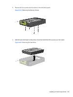
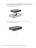
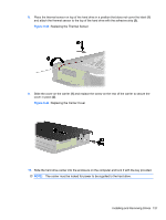
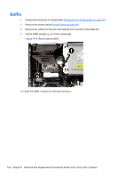
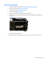
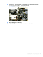
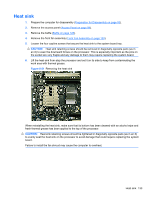
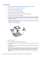
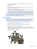
Front I/O and Power Switch Assembly 1. Prepare the computer for disassembly (Preparation for Disassembly on page 93). 2. Remove the access panel (Access Panel on page 94). 3. Remove the front bezel (Front Bezel on page 95). 4. Remove the front fan assembly (Front Fan Assembly on page 129). 5. Remove the black T15 screw (1) that secures the assembly to the chassis. Figure 8-47 Removing the front I/O device/power switch 6. Rotate the drive cage to its upright position. 7. Disconnect the cables (2) from the system board. Figure 8-48 Disconnecting the cables from the system board 130 Chapter 8 Removal and Replacement Procedures Small Form Factor (SFF) Chassis
-
 1
1 -
2
-
3
-
4
-
5
-
6
-
7
-
8
-
9
-
10
-
11
-
12
-
13
-
14
-
15
-
16
-
17
-
18
-
19
-
20
-
21
-
22
-
23
-
24
-
25
-
26
-
27
-
28
-
29
-
30
-
31
-
32
-
33
-
34
-
35
-
36
-
37
-
38
-
39
-
40
-
41
-
42
-
43
-
44
-
45
-
46
-
47
-
48
-
49
-
50
-
51
-
52
-
53
-
54
-
55
-
56
-
57
-
58
-
59
-
60
-
61
-
62
-
63
-
64
-
65
-
66
-
67
-
68
-
69
-
70
-
71
-
72
-
73
-
74
-
75
-
76
-
77
-
78
-
79
-
80
-
81
-
82
-
83
-
84
-
85
-
86
-
87
-
88
-
89
-
90
-
91
-
92
-
93
-
94
-
95
-
96
-
97
-
98
-
99
-
100
-
101
-
102
-
103
-
104
-
105
-
106
-
107
-
108
-
109
-
110
-
111
-
112
-
113
-
114
-
115
-
116
-
117
-
118
-
119
-
120
-
121
-
122
-
123
-
124
-
125
-
126
-
127
-
128
-
129
-
130
-
131
-
132
-
133
-
134
-
 135
135 -
 136
136 -
 137
137 -
 138
138 -
 139
139 -
 140
140 -
 141
141 -
 142
142 -
 143
143 -
 144
144 -
 145
145 -
146
-
147
-
148
-
149
-
150
-
151
-
152
-
153
-
154
-
155
-
156
-
157
-
158
-
159
-
160
-
161
-
162
-
163
-
164
-
165
-
166
-
167
-
168
-
169
-
170
-
171
-
172
-
173
-
174
-
175
-
176
-
177
-
178
-
179
-
180
-
181
-
182
-
183
-
184
-
185
-
186
-
187
-
188
-
189
-
190
-
191
-
192
-
193
-
194
-
195
-
196
-
197
-
198
-
199
-
200
-
201
-
202
-
203
-
204
-
205
-
206
-
207
-
208
-
209
-
210
-
211
-
212
-
213
-
214
-
215
-
216
-
217
-
218
-
219
-
220
-
221
-
222
-
223
-
224
-
225
 |
 |

Front I/O and Power Switch Assembly
1.
Prepare the computer for disassembly (
Preparation for Disassembly
on page
93
).
2.
Remove the access panel (
Access Panel
on page
94
).
3.
Remove the front bezel (
Front Bezel
on page
95
).
4.
Remove the front fan assembly (
Front Fan Assembly
on page
129
).
5.
Remove the black T15 screw
(1)
that secures the assembly to the chassis.
Figure 8-47
Removing the front I/O device/power switch
6.
Rotate the drive cage to its upright position.
7.
Disconnect the cables
(2)
from the system board.
Figure 8-48
Disconnecting the cables from the system board
130
Chapter 8
Removal and Replacement Procedures Small Form Factor (SFF) Chassis