HP 6080 Maintenance & Service Guide: HP Compaq 6000 and 6080 Pro Business - Page 146
System Board
 |
View all HP 6080 manuals
Add to My Manuals
Save this manual to your list of manuals |
Page 146 highlights
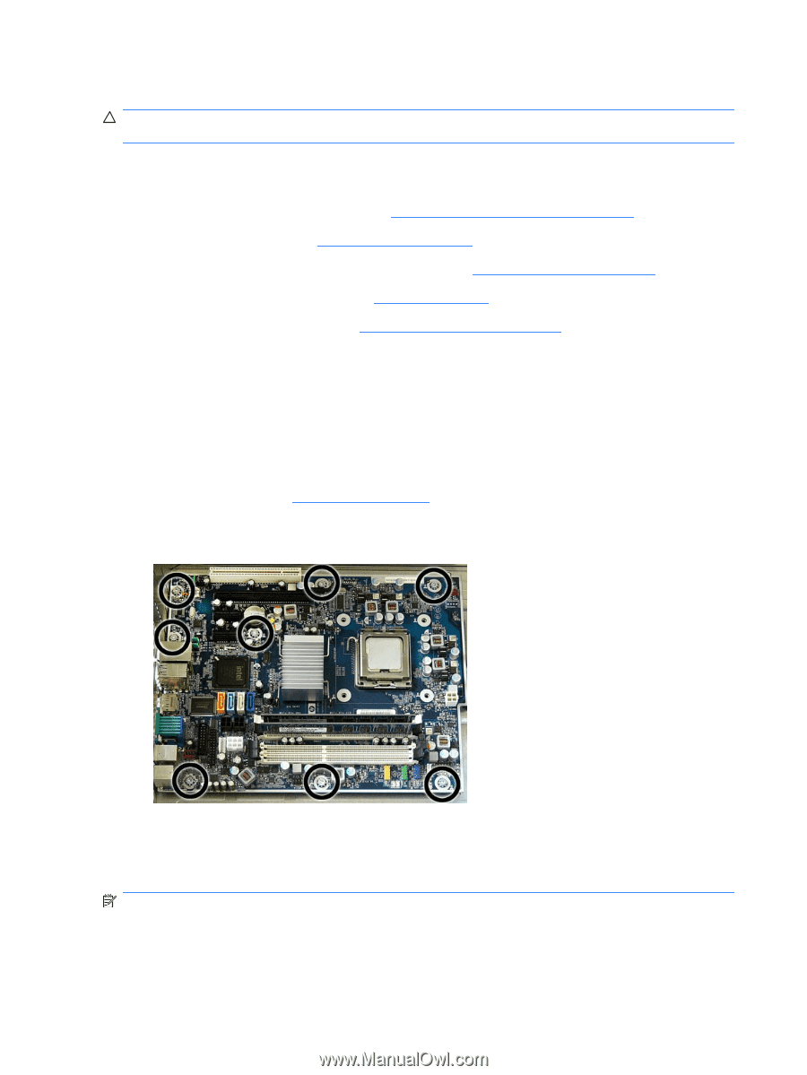
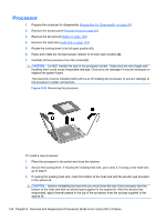
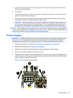
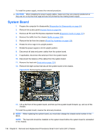
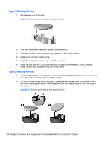
To install the power supply, reverse the removal procedure. CAUTION: When installing the power supply cables, make sure they are properly positioned so they are not cut by the drive cage and are not pinched by the rotating power supply. System Board 1. Prepare the computer for disassembly (Preparation for Disassembly on page 93). 2. Remove the access panel (Access Panel on page 94). 3. Remove all PCI and PCI Express expansion boards (Expansion Cards on page 101). 4. Remove the baffle from the chassis (Baffle on page 128). 5. Remove the fan from the chassis (Front Fan Assembly on page 129). 6. Rotate the drive cage to its upright position. 7. Rotate the power supply to its full upright position. 8. Disconnect all data and power cables from the system board. 9. If applicable, disconnect the serial port from the system board. 10. Disconnect the balance of the cables from the system board. 11. Remove the heat sink (Heat sink on page 133). 12. Remove the eight screws that secure the system board to the chassis. Figure 8-54 Removing the system board 13. Lift up the front of the system board, and then pull the system board forward, up, and out of the chassis. To install the system board, reverse the removal procedure. NOTE: When replacing the system board, you must also change the chassis serial number in the BIOS. NOTE: The heat sink should be installed on the system board before the system board is reinstalled in the chassis. 136 Chapter 8 Removal and Replacement Procedures Small Form Factor (SFF) Chassis
-
 1
1 -
2
-
3
-
4
-
5
-
6
-
7
-
8
-
9
-
10
-
11
-
12
-
13
-
14
-
15
-
16
-
17
-
18
-
19
-
20
-
21
-
22
-
23
-
24
-
25
-
26
-
27
-
28
-
29
-
30
-
31
-
32
-
33
-
34
-
35
-
36
-
37
-
38
-
39
-
40
-
41
-
42
-
43
-
44
-
45
-
46
-
47
-
48
-
49
-
50
-
51
-
52
-
53
-
54
-
55
-
56
-
57
-
58
-
59
-
60
-
61
-
62
-
63
-
64
-
65
-
66
-
67
-
68
-
69
-
70
-
71
-
72
-
73
-
74
-
75
-
76
-
77
-
78
-
79
-
80
-
81
-
82
-
83
-
84
-
85
-
86
-
87
-
88
-
89
-
90
-
91
-
92
-
93
-
94
-
95
-
96
-
97
-
98
-
99
-
100
-
101
-
102
-
103
-
104
-
105
-
106
-
107
-
108
-
109
-
110
-
111
-
112
-
113
-
114
-
115
-
116
-
117
-
118
-
119
-
120
-
121
-
122
-
123
-
124
-
125
-
126
-
127
-
128
-
129
-
130
-
131
-
132
-
133
-
134
-
135
-
136
-
137
-
138
-
139
-
140
-
 141
141 -
 142
142 -
 143
143 -
 144
144 -
 145
145 -
 146
146 -
 147
147 -
 148
148 -
 149
149 -
 150
150 -
 151
151 -
152
-
153
-
154
-
155
-
156
-
157
-
158
-
159
-
160
-
161
-
162
-
163
-
164
-
165
-
166
-
167
-
168
-
169
-
170
-
171
-
172
-
173
-
174
-
175
-
176
-
177
-
178
-
179
-
180
-
181
-
182
-
183
-
184
-
185
-
186
-
187
-
188
-
189
-
190
-
191
-
192
-
193
-
194
-
195
-
196
-
197
-
198
-
199
-
200
-
201
-
202
-
203
-
204
-
205
-
206
-
207
-
208
-
209
-
210
-
211
-
212
-
213
-
214
-
215
-
216
-
217
-
218
-
219
-
220
-
221
-
222
-
223
-
224
-
225
 |
 |