HP 655 HP 655 Notebook PC - Maintenance and Service Guide
HP 655 Manual
 |
View all HP 655 manuals
Add to My Manuals
Save this manual to your list of manuals |
HP 655 manual content summary:
- HP 655 | HP 655 Notebook PC - Maintenance and Service Guide - Page 1
HP 655 Notebook PC Maintenance and Service Guide - HP 655 | HP 655 Notebook PC - Maintenance and Service Guide - Page 2
L.P. AMD, the AMD Arrow logo, and combinations thereof, are trademarks of Advanced Micro Devices, Inc. Bluetooth is a trademark owned by its proprietor and used by Hewlett-Packard Company under license. Microsoft, Windows, and Windows Vista are U.S. registered trademarks of Microsoft Corporation. SD - HP 655 | HP 655 Notebook PC - Maintenance and Service Guide - Page 3
of heat-related injuries or of overheating the device, do not place the device directly on your lap or obstruct the device air vents. Use the device only on a hard, flat surface. Do not allow another hard surface, such as an adjoining optional printer, or a soft surface, such as pillows or rugs - HP 655 | HP 655 Notebook PC - Maintenance and Service Guide - Page 4
iv Safety warning notice - HP 655 | HP 655 Notebook PC - Maintenance and Service Guide - Page 5
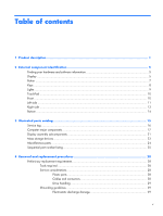
hardware and software information 5 Display ...5 Button ...7 Keys ...8 Lights ...9 TouchPad ...10 Front ...10 Left side ...11 Right side ...13 Bottom ...14 3 Illustrated parts catalog 15 Service tag ...16 Computer major components 17 Display assembly subcomponents 21 Mass storage devices ...23 - HP 655 | HP 655 Notebook PC - Maintenance and Service Guide - Page 6
sink assembly 64 Display assembly ...67 Power connector cable 76 5 Using Setup Utility (BIOS) and System Diagnostics 78 Starting Setup Utility (BIOS) ...78 Updating the BIOS ...78 Determining the BIOS version 79 Downloading a BIOS update 79 Using System Diagnostics ...80 6 Specifications ...81 - HP 655 | HP 655 Notebook PC - Maintenance and Service Guide - Page 7
the computer boot order 87 Backing up and recovering your information 88 Using Windows Backup and Restore 89 Using Windows system restore points 89 When to create restore points 89 Create a system restore point 89 Restore to a previous date and time 90 8 Power cord set requirements 91 - HP 655 | HP 655 Notebook PC - Maintenance and Service Guide - Page 8
viii - HP 655 | HP 655 Notebook PC - Maintenance and Service Guide - Page 9
Panel Description HP 655 Notebook PC ● AMD® E2-1800 processor (1.70-GHz, 1333-MHz, 18 W, dual core; not supported on computer models equipped with Windows® 7 Starter 32-bit operating systems) ● AMD E1-1200 processor (1.40-GHz, 1066-MHz, 18 W, dual core; not supported on computer models equipped - HP 655 | HP 655 Notebook PC - Maintenance and Service Guide - Page 10
E2-1800 processor DDR3-1066-MHz single channel support (DDR3-1600 downgrade to DDR3-1066) on computer models equipped with an AMD E1-1200 or E-300 processor Supports 8192-MB of system RAM in the following configurations: ● 8192-MB (4096-MB×2; not supported on computer models equipped with a 32- bit - HP 655 | HP 655 Notebook PC - Maintenance and Service Guide - Page 11
WiFi Adapter ● Ralink RT3290LE 802.11b/g/n 1×1 WiFi and Bluetooth 4.0 Combo Adapter HP Multi-Format Digital Media reader with push-push technology, supporting: ● Secure Digital (SD) Memory Card ● Secure Digital Extended Capacity (SDxC) Memory Card ● Secure Digital High Capacity (SDHC) Memory Card - HP 655 | HP 655 Notebook PC - Maintenance and Service Guide - Page 12
Operating system Serviceability Description Supports security cable lock Preinstalled: ● Windows® 7 Home Basic 64-bit ● Windows 7 Home Premium 64-bit ● Windows 7 Starter 32-bit (not supported on computer models equipped with a 750-, 640-, or 500-GB hard drive) ● FreeDOS End user replaceable parts - HP 655 | HP 655 Notebook PC - Maintenance and Service Guide - Page 13
drives (SSD), or a secondary hard drive. To find out what software is included on your computer, select Start > All Programs. Display Item (1) (2) Component WLAN antennas (2)* Internal microphone Description Send and receive wireless signals to communicate with WLANs. Records sound. Finding your - HP 655 | HP 655 Notebook PC - Maintenance and Service Guide - Page 14
The antennas are not visible from the outside of the computer. For optimal transmission, keep the areas immediately around the antennas free from obstructions. For wireless regulatory notices, see the section of the Regulatory, Safety, and Environmental Notices that applies to your country or region - HP 655 | HP 655 Notebook PC - Maintenance and Service Guide - Page 15
If the computer has stopped responding and Microsoft Windows shutdown procedures are ineffective, press and hold the power button down for at least 5 seconds to turn off the computer. To learn more about your power settings, select Start > Control Panel > System and Security > Power Options. Button - HP 655 | HP 655 Notebook PC - Maintenance and Service Guide - Page 16
logo key Action keys Windows applications key Description Displays system information when pressed in combination with the fn key. Used in conjunction with hotkeys. Displays the Windows Start menu. Execute frequently used system functions. Displays a shortcut menu for items beneath the pointer - HP 655 | HP 655 Notebook PC - Maintenance and Service Guide - Page 17
(2) Component Caps lock light Power light (3) Wireless light Description On: Caps lock is on, which switches the keys to all capital letters. ● White . ● White: An integrated wireless device, such as a WLAN device and/or a Bluetooth device, is on. ● Amber: All wireless devices are off. Lights 9 - HP 655 | HP 655 Notebook PC - Maintenance and Service Guide - Page 18
TouchPad zone Left TouchPad button Right TouchPad button Component Speakers Description Turns the TouchPad on or off. ● On: The TouchPad is off. ● Off: The TouchPad is on. Moves the on-screen pointer and selects or activates items on the screen. Functions like the left button on an external mouse - HP 655 | HP 655 Notebook PC - Maintenance and Service Guide - Page 19
to cycle on and off during routine operation. Connects a network cable. Connects an optional video or audio device, such as a high-definition television, any compatible digital or audio device. Connects an optional USB device. Connects an optional computer headset microphone, stereo array microphone - HP 655 | HP 655 Notebook PC - Maintenance and Service Guide - Page 20
slot (9) (10) Hard drive light Power light Description Supports the following digital card formats: ● Secure Digital (SD) Memory Card ● Secure Digital Extended Capacity (SDxC) Memory Card ● Secure Digital High Capacity (SDHC) Memory Card ● MultiMediaCard (MMC) Blinking white: The hard drive is - HP 655 | HP 655 Notebook PC - Maintenance and Service Guide - Page 21
are multiple USB ports on the same side, only one USB port will able to support a high power device at a time. ● White: The AC adapter is connected and the battery is charged. ● Amber: The AC adapter is connected and the battery is charging. ● Off: The computer is using DC power. Connects an AC - HP 655 | HP 655 Notebook PC - Maintenance and Service Guide - Page 22
Releases the battery from the battery bay. The memory module/wireless module compartment cover provides access to the memory module compartment, wireless module compartment, keyboard retention screw, and optical drive bay. CAUTION: To prevent an unresponsive system, replace the wireless module only - HP 655 | HP 655 Notebook PC - Maintenance and Service Guide - Page 23
3 Illustrated parts catalog 15 - HP 655 | HP 655 Notebook PC - Maintenance and Service Guide - Page 24
components. The part number helps a service technician to determine what components and parts are needed. This number describes the duration of the warranty period for the computer. This is the alphanumeric identifier used to locate documents, drivers, and support for the computer. 16 Chapter - HP 655 | HP 655 Notebook PC - Maintenance and Service Guide - Page 25
Computer major components Item (1) Component Spare part number Display assembly: The display assembly is spared at the subcomponent level only. For more display assembly spare part information, see Display assembly subcomponents on page 21. Computer major components 17 - HP 655 | HP 655 Notebook PC - Maintenance and Service Guide - Page 26
replacement thermal material): For use on computer models equipped with an AMD E2-1800 processor (1.70-GHz, 1333-MHz, 18 W, dual core, UMA graphics subsystem memory) For use on computer models equipped with an AMD E1-1200 processor (1.40-GHz, 1066-MHz, 18 W, dual core, UMA graphics subsystem memory - HP 655 | HP 655 Notebook PC - Maintenance and Service Guide - Page 27
equipped with an AMD E-300 processor (1.30-GHz, 1066-MHz, 18 W, dual core, UMA graphics subsystem memory) 689073-001 Fan/heat sink assembly (includes replacement thermal material) 688306-001 Power connector cable (includes bracket) 686258-001 Base enclosure (includes battery cover lock latch - HP 655 | HP 655 Notebook PC - Maintenance and Service Guide - Page 28
Item (19) (20) Component Spare part number Hard drive compartment cover (includes one captive screw, secured by a C-clip) Memory module/wireless module compartment cover (includes one captive screw, secured by a C-clip) 20 Chapter 3 Illustrated parts catalog - HP 655 | HP 655 Notebook PC - Maintenance and Service Guide - Page 29
Display bezel Webcam/microphone module (includes double-sided adhesive) 15.6-in, LED, SVA, HD, BrightView display panel Display Hinge Kit, includes: Left and right display hinge covers Left and right display hinges and vertical support brackets Spare part number 686254-001 686285-001 687700-001 - HP 655 | HP 655 Notebook PC - Maintenance and Service Guide - Page 30
Item (6) (7) (8) Component Spare part number Display panel cable (includes webcam/microphone module cable) 687700-001 Antenna Kit (includes wireless antenna left and right (main and auxiliary) cables and transceivers) 686249-001 Display enclosure 687698-001 Rubber Kit (not illustrated, - HP 655 | HP 655 Notebook PC - Maintenance and Service Guide - Page 31
Mass storage devices Item (1) (2a) (2b) (3) Component Spare part number Hard drive (does not 001 Hard drive bracket Hard drive connector cable Hard drive bracket screws (not illustrated) DVD±RW Double-Layer with SuperMulti Drive (includes optical drive bezel and optical drive bracket) 686268 - HP 655 | HP 655 Notebook PC - Maintenance and Service Guide - Page 32
Miscellaneous parts Component 65-W HP Smart AC adapter (RC, V, 3-wire) Power cord (3-pin, black, 1.83-m): For use in Denmark For use in Europe For use in Israel For use in Italy For use in North America For use in South Africa For use in Switzerland For use in the United Kingdom and Singapore Screw - HP 655 | HP 655 Notebook PC - Maintenance and Service Guide - Page 33
-ion battery 593554-001 6-cell, 55-Wh, 2.55-Ah, Li-ion battery 609939- memory module (PC3, 12800, 1600-MHz) 646125-001 Keyboard for use in the United States (includes keyboard cable) 646125-031 Keyboard for use in the United Kingdom and Singapore (includes keyboard cable) 646125-041 Keyboard - HP 655 | HP 655 Notebook PC - Maintenance and Service Guide - Page 34
keyboard cable) 646125-DJ1 Keyboard for use in Greece (includes keyboard cable) 652972-001 2-GB memory module (PC3, 12800, 1600-MHz) 655795-001 Atheros 9485GN 802.11b/g/n 1×1 WiFi and 3012 Bluetooth wireless antenna left and right (main and auxiliary) cables and transceivers) 686253-001 Base - HP 655 | HP 655 Notebook PC - Maintenance and Service Guide - Page 35
an AMD E1-1200 processor (1.40-GHz, 1066-MHz, 18 W, dual core, UMA graphics subsystem memory; includes processor and replacement thermal material) 689072-001 System board for use on computer models equipped with an AMD E2-1800 processor (1.70-GHz, 1333-MHz, 18 W, dual core, UMA graphics subsystem - HP 655 | HP 655 Notebook PC - Maintenance and Service Guide - Page 36
plastic parts. Apply pressure only at the points designated in the maintenance instructions. Cables and connectors CAUTION: When servicing the computer, be sure that cables are placed in their proper locations during the reassembly process. Improper cable placement can damage the computer. Cables - HP 655 | HP 655 Notebook PC - Maintenance and Service Guide - Page 37
, turn the computer on, and then shut it down through the operating system. products that have magnetic fields, such as monitors or speakers. Avoid exposing a drive to Networks built into many integrated circuits provide some protection, but in many cases, ESD contains enough power to alter device - HP 655 | HP 655 Notebook PC - Maintenance and Service Guide - Page 38
DIPS from Styrofoam Removing bubble pack from PCB Packing PCBs in foam-lined box Typical electrostatic voltage levels Relative humidity 10% 40% 35,000 V 15,000 V 12,000 V 5,000 V 6,000 V 800 V 2,000 V 700 V 11,500 V 4,000 V 14,500 V 5,000 V 26,500 V 20,000 V 21,000 V 11,000 V 55 - HP 655 | HP 655 Notebook PC - Maintenance and Service Guide - Page 39
the parts arrive at static-free workstations. ● Place items on and equipment. ● Use conductive field service tools, such as cutters, screwdrivers materials. ● Keep the work area free of nonconductive materials, such as -free workstations. ● Avoid contact with pins, leads, or circuitry. ● Turn off - HP 655 | HP 655 Notebook PC - Maintenance and Service Guide - Page 40
, wear a wrist strap connected to a grounded system. Wrist straps are flexible straps with a minimum , or boot straps) can be used at standing workstations and are compatible with most types of shoes or boots. On ties to the ground ● Field service kits ● Static awareness labels replacement procedures - HP 655 | HP 655 Notebook PC - Maintenance and Service Guide - Page 41
location during removal and replacement. Service tag When ordering parts or requesting information, provide the computer serial number and model number provided on the service tag. It is necessary to remove the battery to obtain these numbers. See Battery on page 35 for battery removal instructions - HP 655 | HP 655 Notebook PC - Maintenance and Service Guide - Page 42
This is the alphanumeric identifier used to locate documents, drivers, and support for the computer. Computer feet The base enclosure, as indicated in the illustration below. These rubber feet are available in the Rubber Kit, spare part number 686276-001. 34 Chapter 4 Removal and replacement - HP 655 | HP 655 Notebook PC - Maintenance and Service Guide - Page 43
installed and sealed at the factory. A broken battery seal voids the computer and battery warranties. The computer has an internal rechargeable battery that can be replaced only by an authorized service provider. Before disassembling the computer, follow these steps: 1. Turn off the computer. If you - HP 655 | HP 655 Notebook PC - Maintenance and Service Guide - Page 44
system. 2. Disconnect the power from the computer by unplugging the power cord from the computer. 3. Disconnect all external devices from the computer. 4. Remove the battery (see Battery on page 35). Remove the memory module: 1. Loosen the captive screw (1) that secures the memory module/wireless - HP 655 | HP 655 Notebook PC - Maintenance and Service Guide - Page 45
Adapter Ralink RT3290LE 802.11b/g/n 1×1 WiFi and Bluetooth 4.0 Combo Adapter Spare part number 690019-001 675794-001 655795-001 657325-001 670691-001 691415-001 690020-001 CAUTION: To prevent an unresponsive system, replace the wireless module only with a wireless module authorized for use in the - HP 655 | HP 655 Notebook PC - Maintenance and Service Guide - Page 46
Remove the battery (see Battery on page 35). 5. Remove the memory module/wireless module compartment cover (see Memory module on Remove the Phillips PM2.0×3.0 screw (2) that secures the WLAN module to the system board. (The WLAN module tilts up.) 3. Remove the WLAN module by replacement procedures - HP 655 | HP 655 Notebook PC - Maintenance and Service Guide - Page 47
the operating system. 2. Disconnect the power from the computer by unplugging the power cord from the computer. 3. Disconnect all external devices from the computer. 4. Remove the battery (see Battery on page 35). 5. Remove the memory module/wireless module compartment cover (see Memory module on - HP 655 | HP 655 Notebook PC - Maintenance and Service Guide - Page 48
Remove the keyboard: 1. Remove the Phillips PM2.5×4.0 screw that secures the keyboard to the computer. 2. Rest and secure the computer on its left side. 3. Partially open the computer. 40 Chapter 4 Removal and replacement procedures - HP 655 | HP 655 Notebook PC - Maintenance and Service Guide - Page 49
a screw driver or similar thin tool into the keyboard release hole, and then press on the back of the keyboard until the keyboard disengages from the computer. 5. Turn the computer right-side up with the front toward you. 6. Lift the rear edge of the keyboard (1), and then swing the keyboard up and - HP 655 | HP 655 Notebook PC - Maintenance and Service Guide - Page 50
7. Release the zero insertion force (ZIF) connector (1) to which the keyboard cable is attached, and then disconnect the keyboard cable (2) from the system board. 8. Remove the keyboard (3). Reverse this procedure to install the keyboard. 42 Chapter 4 Removal and replacement procedures - HP 655 | HP 655 Notebook PC - Maintenance and Service Guide - Page 51
the operating system. 2. Disconnect the power from the computer by unplugging the power cord from the computer. 3. Disconnect all external devices from the computer. 4. Remove the battery (see Battery on page 35). 5. Remove the memory module/wireless module compartment cover (see Memory module on - HP 655 | HP 655 Notebook PC - Maintenance and Service Guide - Page 52
tray. 5. Use a flat-blade screw driver or similar tool to press on the optical drive bezel tab (2) to release the optical drive bezel. 6. Release the left side of the optical drive bezel (3). 7. Remove the optical drive bezel (4). 8. If it is necessary to replace the optical drive bracket, position - HP 655 | HP 655 Notebook PC - Maintenance and Service Guide - Page 53
the operating system. 2. Disconnect the power from the computer by unplugging the power cord from the computer. 3. Disconnect all external devices from the computer. 4. Remove the battery (see Battery on page 35). 5. Remove the memory module/wireless module compartment cover (see Memory module on - HP 655 | HP 655 Notebook PC - Maintenance and Service Guide - Page 54
in the Cover Kit, spare part number 686272-001. 4. Disconnect the hard drive connector cable (1) from the system board, and then release the cable from the clip (2) built into the base enclosure. 5. Remove the four Phillips PM2.5×4.0 screws (3) that secure the hard drive to the computer. 6. Remove - HP 655 | HP 655 Notebook PC - Maintenance and Service Guide - Page 55
screws are available in the Hard Drive Hardware Kit, spare part number 686261-001. Reverse this procedure to reassemble and install the hard drive. Component replacement procedures 47 - HP 655 | HP 655 Notebook PC - Maintenance and Service Guide - Page 56
the operating system. 2. Disconnect the power from the computer by unplugging the power cord from the computer. 3. Disconnect all external devices from the computer. 4. Remove the battery (see Battery on page 35). 5. Remove the memory module/wireless module compartment cover (see Memory module on - HP 655 | HP 655 Notebook PC - Maintenance and Service Guide - Page 57
devices from the computer. 4. Remove the battery (see Battery on page 35), and then remove the following components: a. Memory module/wireless module compartment cover (see Memory module on page 36) b. Keyboard (see Keyboard on page 39) c. Hard drive (see Hard drive on page 45) NOTE: When replacing - HP 655 | HP 655 Notebook PC - Maintenance and Service Guide - Page 58
computer. 4. Turn the computer right side up, with the front toward you. 5. Open the computer. 6. Release the ZIF connector to which the power button board cable is connected, and then disconnect the power button board cable (1) from the system board. 50 Chapter 4 Removal and replacement procedures - HP 655 | HP 655 Notebook PC - Maintenance and Service Guide - Page 59
button board cable is connected, and then disconnect the TouchPad button board cable (2) from the system board. 8. Remove the Phillips PM2.0×2.5 screw (1) and the three Phillips PM2.5×6.5 screws (2) that right sides of the top cover detach from the base enclosure. Component replacement procedures 51 - HP 655 | HP 655 Notebook PC - Maintenance and Service Guide - Page 60
from the computer. 3. Disconnect all external devices from the computer. 4. Remove the battery (see Battery on page 35), and then remove the following components: a. Memory module/wireless module compartment cover (see Memory module on page 36) b. Keyboard (see Keyboard on page 39) c. Hard drive - HP 655 | HP 655 Notebook PC - Maintenance and Service Guide - Page 61
from the computer. 3. Disconnect all external devices from the computer. 4. Remove the battery (see Battery on page 35), and then remove the following components: a. Memory module/wireless module compartment cover (see Memory module on page 36) b. Keyboard (see Keyboard on page 39) c. Hard drive - HP 655 | HP 655 Notebook PC - Maintenance and Service Guide - Page 62
Remove the TouchPad button board: 1. Turn the top cover upside down, with the front toward you. 2. Detach the TouchPad button board cable (1) from the TouchPad. (The cover. Lift the rear edge of the TouchPad button board (2) until it rests at an angle. 54 Chapter 4 Removal and replacement procedures - HP 655 | HP 655 Notebook PC - Maintenance and Service Guide - Page 63
6. Remove the TouchPad button board (3) by sliding it away from the top cover at an angle. Reverse this procedure to install the TouchPad button board. Component replacement procedures 55 - HP 655 | HP 655 Notebook PC - Maintenance and Service Guide - Page 64
from the computer. 3. Disconnect all external devices from the computer. 4. Remove the battery (see Battery on page 35), and then remove the following components: a. Memory module/wireless module compartment cover (see Memory module on page 36) b. Keyboard (see Keyboard on page 39) c. Hard drive - HP 655 | HP 655 Notebook PC - Maintenance and Service Guide - Page 65
4. Remove the optical drive connector cable (4). Reverse this procedure to install the optical drive connector cable. Component replacement procedures 57 - HP 655 | HP 655 Notebook PC - Maintenance and Service Guide - Page 66
from the computer. 3. Disconnect all external devices from the computer. 4. Remove the battery (see Battery on page 35), and then remove the following components: a. Memory module/wireless module compartment cover (see Memory module on page 36) b. Keyboard (see Keyboard on page 39) c. Hard drive - HP 655 | HP 655 Notebook PC - Maintenance and Service Guide - Page 67
4. Remove the speakers (4). Reverse this procedure to install the speakers. Component replacement procedures 59 - HP 655 | HP 655 Notebook PC - Maintenance and Service Guide - Page 68
from the computer. 3. Disconnect all external devices from the computer. 4. Remove the battery (see Battery on page 35), and then remove the following components: a. Memory module/wireless module compartment cover (see Memory module on page 36) b. Keyboard (see Keyboard on page 39) c. Hard drive - HP 655 | HP 655 Notebook PC - Maintenance and Service Guide - Page 69
3. Remove the USB board (3). Reverse this procedure to install the USB board. Component replacement procedures 61 - HP 655 | HP 655 Notebook PC - Maintenance and Service Guide - Page 70
the processor and replacement thermal material. Description Spare part number For use on computer models equipped with an AMD E2-1800 processor (1.70-GHz, 1333-MHz, 688304-001 18 W, dual core, UMA graphics subsystem memory) For use on computer models equipped with an AMD E1-1200 processor (1.40 - HP 655 | HP 655 Notebook PC - Maintenance and Service Guide - Page 71
system board. (1) Speaker cable (2) Optical drive connector cable (3) Display panel cable (4) USB board cable (5) Power connector cable 2. Remove the three Phillips PM2.5×6.0 screws (1) that secure the system board to the base enclosure. 3. Lift the right side of the system - HP 655 | HP 655 Notebook PC - Maintenance and Service Guide - Page 72
external devices from the computer. 4. Remove the battery (see Battery on page 35), and then remove the following components: a. Memory module/wireless module compartment cover (see Memory module on page 36) b. Keyboard (see Keyboard on page 39) c. Hard drive (see Hard drive on page 45) 64 Chapter - HP 655 | HP 655 Notebook PC - Maintenance and Service Guide - Page 73
is removed. Replacement thermal material is included with the processor heat sink and system board spare part kits. NOTE: The following illustration shows the replacement thermal material locations. Thermal paste is used on the processor (1) and the heat sink section (2) that services it. Component - HP 655 | HP 655 Notebook PC - Maintenance and Service Guide - Page 74
Reverse this procedure to install the fan/heat sink assembly. 66 Chapter 4 Removal and replacement procedures - HP 655 | HP 655 Notebook PC - Maintenance and Service Guide - Page 75
the computer. 3. Disconnect all external devices from the computer. 4. Remove the battery (see Battery on page 35). 5. Disconnect the wireless antenna cables from the WLAN module (see Memory module on page 36). 6. Remove the following components: a. Keyboard (see Keyboard on page 39) b. Hard drive - HP 655 | HP 655 Notebook PC - Maintenance and Service Guide - Page 76
2. Release the wireless antenna cables (2) from the clips and routing channel built into the base enclosure. CAUTION: Support the display assembly when removing the following screws. Failure to support the display assembly can result in damage to the display assembly and other computer components. - HP 655 | HP 655 Notebook PC - Maintenance and Service Guide - Page 77
4. Remove the display assembly (2). 5. If it is necessary to replace the display bezel or any of the display assembly subcomponents: a. Remove the two display bezel screw the top edge (5) of the display bezel until the bezel disengages from the display enclosure. Component replacement procedures 69 - HP 655 | HP 655 Notebook PC - Maintenance and Service Guide - Page 78
c. Remove the display bezel (6). The display bezel is available using spare part number 686254-001. 6. If it is necessary to replace the display hinge covers: a. Remove the two Phillips PM2.5×4.0 screws (1) that secure the display hinge covers to the display enclosure. b. Remove the display hinge - HP 655 | HP 655 Notebook PC - Maintenance and Service Guide - Page 79
7. If it is necessary to replace the display panel: a. Release the display panel cable (1) from and forward until it rests upside down in front of the display enclosure. d. Release the adhesive support strip (1) that secures the display panel cable to the display panel. e. Detach the display panel - HP 655 | HP 655 Notebook PC - Maintenance and Service Guide - Page 80
from the display panel. g. Remove the display panel. The display panel is available using spare part number 687700-001. 8. If it is necessary to replace the display hinges: a. Remove the six Phillips PM2.0×3.5 screws (1) that secure the display hinges to the display panel. 72 Chapter 4 Removal and - HP 655 | HP 655 Notebook PC - Maintenance and Service Guide - Page 81
using spare part number 686262-001. 9. If it is necessary to replace the display panel cable: a. Detach the display panel cable (1) from the sided tape in multiple locations.) b. Disconnect the webcam/microphone cable (2) from the webcam/microphone module. Component replacement procedures 73 - HP 655 | HP 655 Notebook PC - Maintenance and Service Guide - Page 82
c. Remove the display panel cable (3). The display panel cable is available using spare part number 686256-001 and includes the webcam/microphone cable. 74 Chapter 4 Removal and replacement procedures - HP 655 | HP 655 Notebook PC - Maintenance and Service Guide - Page 83
models may be equipped one or two sets of wireless antenna cables and transceivers. 11. If it is necessary to replace the wireless antenna cables and transceivers: a. Detach the wireless antenna transceivers (1) from the display enclosure. (The wireless antenna transceivers are attached to the - HP 655 | HP 655 Notebook PC - Maintenance and Service Guide - Page 84
from the computer. 3. Disconnect all external devices from the computer. 4. Remove the battery (see Battery on page 35), and then remove the following components: a. Memory module/wireless module compartment cover (see Memory module on page 36) b. Keyboard (see Keyboard on page 39) c. Hard drive - HP 655 | HP 655 Notebook PC - Maintenance and Service Guide - Page 85
3. Remove the power connector bracket (3). 4. Remove the power connector cable (4). Reverse this procedure to install the power connector cable. Component replacement procedures 77 - HP 655 | HP 655 Notebook PC - Maintenance and Service Guide - Page 86
, display, keyboard, mouse, and printer). Setup Utility (BIOS) includes settings for the types of devices installed, the startup sequence of the computer, and the amount of system and extended memory. Starting Setup Utility (BIOS) To start Setup Utility (BIOS), follow these steps: 1. Turn on or - HP 655 | HP 655 Notebook PC - Maintenance and Service Guide - Page 87
the network administrator before installing any software updates, especially system BIOS updates. BIOS installation procedures vary. Follow any instructions that are displayed on the screen after the download is complete. If no instructions are displayed, follow these steps: 1. Open Windows Explorer - HP 655 | HP 655 Notebook PC - Maintenance and Service Guide - Page 88
, filename.exe). The BIOS installation begins. 5. Complete the installation by following the on-screen instructions. NOTE: After a message on the screen reports a successful installation, you can delete the downloaded file from your hard drive. Using System Diagnostics System Diagnostics allows you - HP 655 | HP 655 Notebook PC - Maintenance and Service Guide - Page 89
6 Specifications Computer specifications Metric U.S. Dimensions Width 37.60 cm 14.80 in Depth 24.70 cm % to 90% Nonoperating 5% to 95% Maximum altitude (unpressurized) Operating -15 m to 3,048 m -50 ft to 10,000 ft Nonoperating -15 m to 12,192 m -50 ft to 40,000 ft NOTE: Applicable - HP 655 | HP 655 Notebook PC - Maintenance and Service Guide - Page 90
power consumption Viewing angle Metric U.S. 19.6 cm 34.7 cm 39.8 cm Up to 16.8 million 200:1 (typical) 250 nits (typical) 7.72 in 13.66 in 15.67 in 0.197 × 0.197 mm 1366 × 768 RGB vertical stripe LED 80 × 25 3.46 W ±65° horizontal, +50° vertical (typical) 82 Chapter - HP 655 | HP 655 Notebook PC - Maintenance and Service Guide - Page 91
ATA security ATA security Seek times (typical read, including setting) Single track 1.5 ms 1.5 ms 1.5 ms Average ( Maximum 22 ms 22 ms 22 ms Logical blocks 1,250,269,655 976,773,168 628,142,448 Disk rotational speed 5400 rpm 5400 support for details. Hard drive specifications 83 - HP 655 | HP 655 Notebook PC - Maintenance and Service Guide - Page 92
program or driver Restore In the event of hard drive failure, to restore your system to its factory image you must use a set of recovery discs or a recovery flash drive that you have created using HP Recovery Manager. HP recommends that you use HP Recovery Manager immediately after software setup to - HP 655 | HP 655 Notebook PC - Maintenance and Service Guide - Page 93
Manager, you will be prompted to continue the backup creation process. To create a set of recovery discs or a recovery flash drive: 1. Select Start > All Programs > HP Help and Support > HP Recovery Manager > HP Recovery Media Creation. 2. Follow the on-screen instructions. Creating recovering - HP 655 | HP 655 Notebook PC - Maintenance and Service Guide - Page 94
the ESC key for Startup Menu" message is displayed at the bottom of the screen. Then, press f11 while the "F11 (System Recovery)" message is displayed on the screen. 2. Click System Recovery in the HP Recovery Manager window. 3. Follow the on-screen instructions. 86 Chapter 7 Backup and recovery - HP 655 | HP 655 Notebook PC - Maintenance and Service Guide - Page 95
Follow the on-screen instructions. Changing the computer boot order To change the boot order for recovery discs: 1. Restart the computer. 2. Press esc while the computer is restarting, and then press f9 for boot options. 3. Select Internal CD/DVD ROM Drive from the boot options window. To change the - HP 655 | HP 655 Notebook PC - Maintenance and Service Guide - Page 96
restore points, see the "Using Windows system restore points" section. ● Store personal files in the Documents library and back up this folder periodically. ● Save customized settings in a window, toolbar, or menu bar by taking a screen shot of your settings. The screen shot can be a time-saver - HP 655 | HP 655 Notebook PC - Maintenance and Service Guide - Page 97
Panel > System and Security > Backup and Restore. 2. Follow the on-screen instructions to schedule and create a backup. NOTE: Windows includes the software, running utilities, or changing Windows settings. For more information, see Help and Support. Using Windows system restore points A system - HP 655 | HP 655 Notebook PC - Maintenance and Service Guide - Page 98
functioning optimally, follow these steps: 1. Select Start > Control Panel > System and Security > System. 2. In the left pane, click System protection. 3. Click the System Protection tab. 4. Click System Restore. 5. Follow the on-screen instructions. NOTE: If you revert to a restore point and then - HP 655 | HP 655 Notebook PC - Maintenance and Service Guide - Page 99
for evaluation in the country or region where the power cord set will be used. ● The power cord sets must have a minimum current capacity of 10 amps and a nominal voltage rating of 125 or 250 V AC, as required by the power system of each country or region. ● The appliance coupler must meet the - HP 655 | HP 655 Notebook PC - Maintenance and Service Guide - Page 100
Requirements for specific countries and regions Country/region Accredited agency Applicable note number Australia EANSW the country or region where it will be used. 5. The flexible cord must be Type VCTF, 3-conductor, 0.75-mm² conductor size. Power cord set fittings (appliance coupler and wall - HP 655 | HP 655 Notebook PC - Maintenance and Service Guide - Page 101
in general household waste. Follow the local laws and regulations in your area for battery disposal. HP encourages customers to recycle used electronic hardware, HP original print cartridges, and rechargeable batteries. For more information about recycling programs, see the HP Web site at http://www - HP 655 | HP 655 Notebook PC - Maintenance and Service Guide - Page 102
jack 11 B base enclosure, spare part number 19, 26 battery removal 35 spare part numbers 19, 25, 35 battery bay 14 battery release latch 14 key 8 Ethernet, product description 2 external monitor port 11 F fan/heat sink assembly removal 64 spare part number 19, 27, 64 feet locations 34 spare part - HP 655 | HP 655 Notebook PC - Maintenance and Service Guide - Page 103
, product description 3 processor product description 1 product description audio 2 chipset 1 display panel 1 Ethernet 2 external media cards 3 graphics 1 hard drive 2 keyboard 3 memory module 2 microphone 2 operating system 4 optical drive 2 pointing device 3 ports 3 power requirements 3 Index 95 - HP 655 | HP 655 Notebook PC - Maintenance and Service Guide - Page 104
considerations cables 28 connectors 28 plastic parts 28 service tag 16, 33 serviceability, product description 4 speakers location 10 removal 58 spare part number 18, 27, 58 specifications computer 81 display 82 hard drive 83 system board removal 62 spare part numbers 18, 27, 62 spare part number - HP 655 | HP 655 Notebook PC - Maintenance and Service Guide - Page 105
-
 1
1 -
 2
2 -
 3
3 -
 4
4 -
 5
5 -
 6
6 -
 7
7 -
8
-
9
-
10
-
11
-
12
-
13
-
14
-
15
-
16
-
17
-
18
-
19
-
20
-
21
-
22
-
23
-
24
-
25
-
26
-
27
-
28
-
29
-
30
-
31
-
32
-
33
-
34
-
35
-
36
-
37
-
38
-
39
-
40
-
41
-
42
-
43
-
44
-
45
-
46
-
47
-
48
-
49
-
50
-
51
-
52
-
53
-
54
-
55
-
56
-
57
-
58
-
59
-
60
-
61
-
62
-
63
-
64
-
65
-
66
-
67
-
68
-
69
-
70
-
71
-
72
-
73
-
74
-
75
-
76
-
77
-
78
-
79
-
80
-
81
-
82
-
83
-
84
-
85
-
86
-
87
-
88
-
89
-
90
-
91
-
92
-
93
-
94
-
95
-
96
-
97
-
98
-
99
-
100
-
101
-
102
-
103
-
104
-
105
 |
 |

HP 655 Notebook PC
Maintenance and Service Guide