HP 7200 HP Pavilion dv4000 Notebook PCs, Compaq Presario V4000 Notebook PCs, a - Page 110
Description, of Screws Removed, Processor, Switch Cover, Keyboard, Display Assembly
 |
View all HP 7200 manuals
Add to My Manuals
Save this manual to your list of manuals |
Page 110 highlights
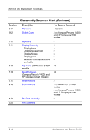
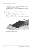
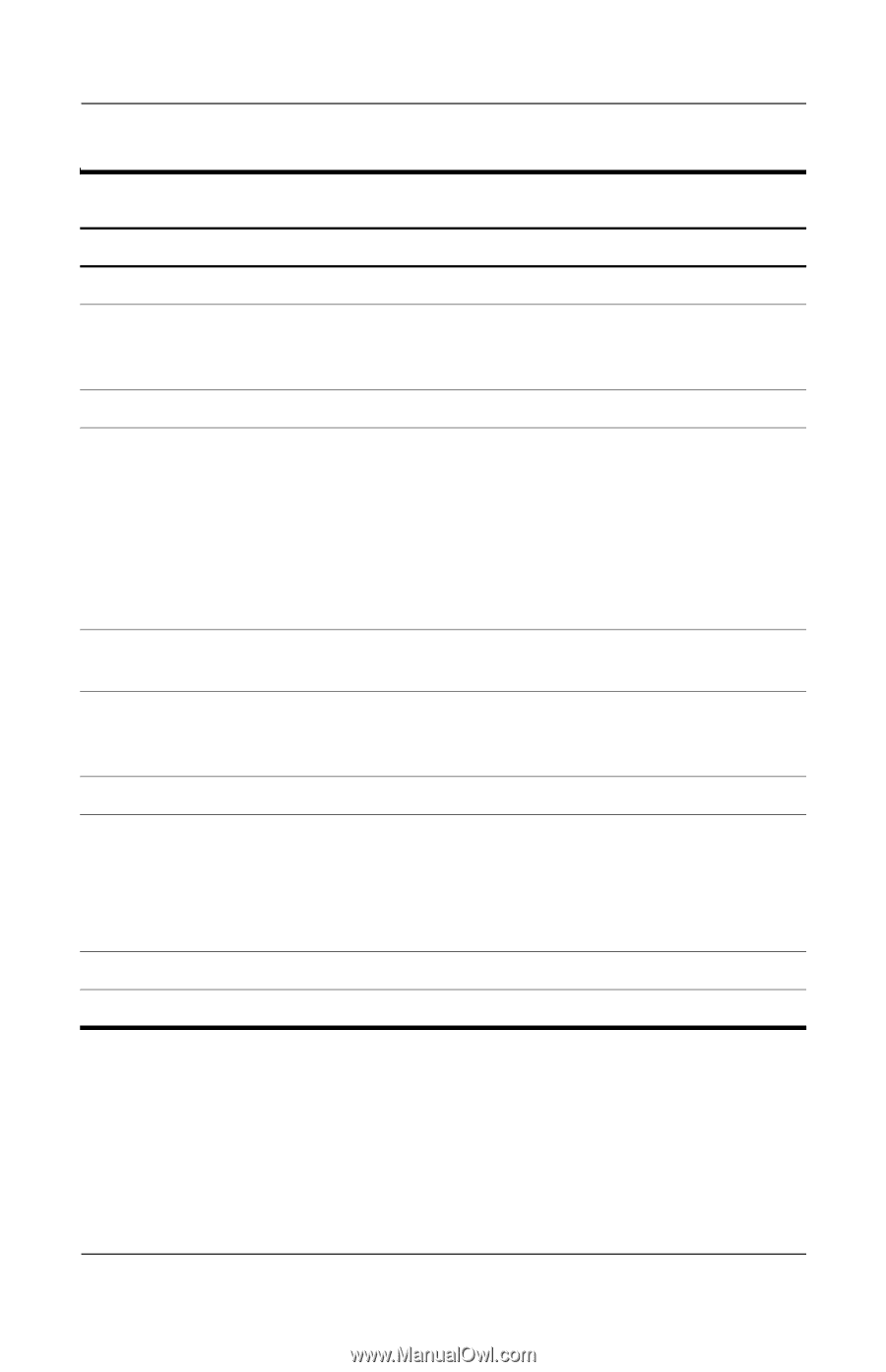
Removal and Replacement Procedures Section 5.11 512 5.13 5.14 5.15 5.16 5.17 5.18 5.19 5.20 Disassembly Sequence Chart (Continued) Description Processor Switch Cover Keyboard Display Assembly Display bezel Display release hook Display hinges Display panel Wireless antenna transceiver and cable Top Cover (HP Pavilion dv4200 models) Base Enclosure (Compaq Presario V4200 and HP Compaq nx7220 models) Modem Board System Board PC Card Assembly Fan Assembly # of Screws Removed 1 loosened 3 on Compaq Presario V4200 and HP Compaq nx7220 models 4 6 6 2 6 6 0 16 16 2 8 on HP Pavilion dv4200 models 4 on Compaq Presario V4200 and HP Compaq nx7220 models 2 7 5-4 Maintenance and Service Guide
-
 1
1 -
2
-
3
-
4
-
5
-
6
-
7
-
8
-
9
-
10
-
11
-
12
-
13
-
14
-
15
-
16
-
17
-
18
-
19
-
20
-
21
-
22
-
23
-
24
-
25
-
26
-
27
-
28
-
29
-
30
-
31
-
32
-
33
-
34
-
35
-
36
-
37
-
38
-
39
-
40
-
41
-
42
-
43
-
44
-
45
-
46
-
47
-
48
-
49
-
50
-
51
-
52
-
53
-
54
-
55
-
56
-
57
-
58
-
59
-
60
-
61
-
62
-
63
-
64
-
65
-
66
-
67
-
68
-
69
-
70
-
71
-
72
-
73
-
74
-
75
-
76
-
77
-
78
-
79
-
80
-
81
-
82
-
83
-
84
-
85
-
86
-
87
-
88
-
89
-
90
-
91
-
92
-
93
-
94
-
95
-
96
-
97
-
98
-
99
-
100
-
101
-
102
-
103
-
104
-
 105
105 -
 106
106 -
 107
107 -
 108
108 -
 109
109 -
 110
110 -
 111
111 -
 112
112 -
 113
113 -
 114
114 -
 115
115 -
116
-
117
-
118
-
119
-
120
-
121
-
122
-
123
-
124
-
125
-
126
-
127
-
128
-
129
-
130
-
131
-
132
-
133
-
134
-
135
-
136
-
137
-
138
-
139
-
140
-
141
-
142
-
143
-
144
-
145
-
146
-
147
-
148
-
149
-
150
-
151
-
152
-
153
-
154
-
155
-
156
-
157
-
158
-
159
-
160
-
161
-
162
-
163
-
164
-
165
-
166
-
167
-
168
-
169
-
170
-
171
-
172
-
173
-
174
-
175
-
176
-
177
-
178
-
179
-
180
-
181
-
182
-
183
-
184
-
185
-
186
-
187
-
188
-
189
-
190
-
191
-
192
-
193
-
194
-
195
-
196
-
197
-
198
-
199
-
200
-
201
-
202
-
203
-
204
-
205
-
206
-
207
-
208
-
209
-
210
-
211
-
212
-
213
-
214
-
215
-
216
-
217
-
218
-
219
-
220
-
221
-
222
-
223
-
224
-
225
-
226
-
227
-
228
-
229
-
230
-
231
-
232
-
233
-
234
-
235
-
236
-
237
-
238
-
239
-
240
-
241
-
242
-
243
-
244
-
245
-
246
-
247
-
248
-
249
-
250
-
251
-
252
-
253
-
254
-
255
-
256
-
257
-
258
-
259
-
260
-
261
-
262
-
263
-
264
-
265
-
266
-
267
-
268
-
269
-
270
-
271
-
272
-
273
 |
 |
5–4
Maintenance and Service Guide
Removal and Replacement Procedures
Section
Description
# of Screws Removed
5.11
Processor
1 loosened
512
Switch Cover
3 on Compaq Presario V4200
and HP Compaq nx7220
models
5.13
Keyboard
4
5.14
Display Assembly
Display bezel
Display release hook
Display hinges
Display panel
Wireless antenna transceiver
and cable
6
6
2
6
6
0
5.15
Top Cover
(HP Pavilion dv4200
models)
16
5.16
Base Enclosure
(Compaq Presario V4200 and
HP Compaq nx7220 models)
16
5.17
Modem Board
2
5.18
System Board
8 on HP Pavilion dv4200
models
4 on Compaq Presario V4200
and HP Compaq nx7220
models
5.19
PC Card Assembly
2
5.20
Fan Assembly
7
Disassembly Sequence Chart
(Continued)