HP 7200 HP Pavilion dv4000 Notebook PCs, Compaq Presario V4000 Notebook PCs, a - Page 125
Remove the Mini PCI communications module by pulling the, communications module.
 |
View all HP 7200 manuals
Add to My Manuals
Save this manual to your list of manuals |
Page 125 highlights
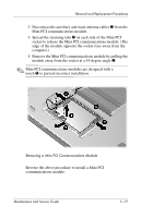
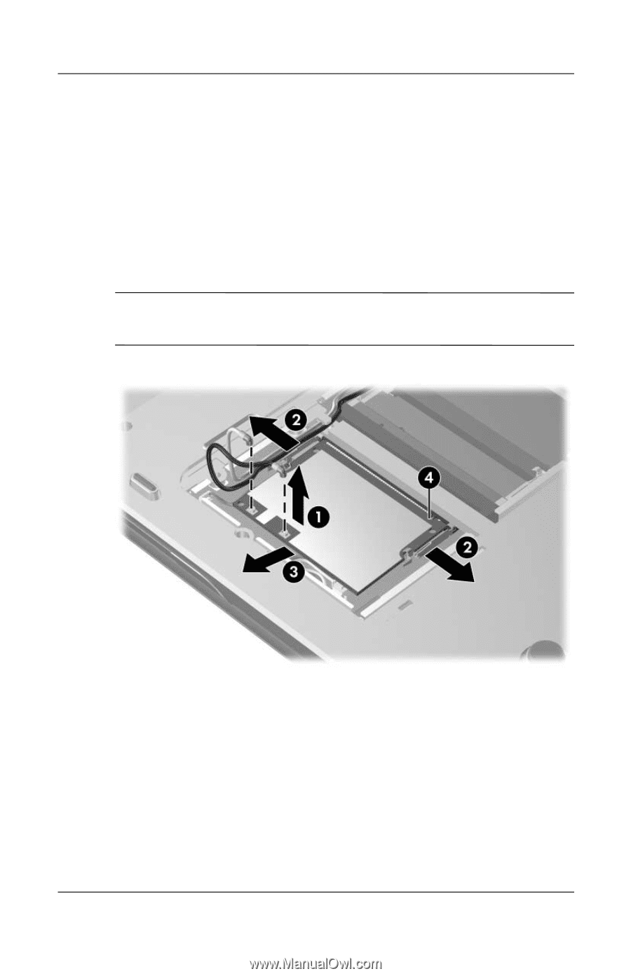
Removal and Replacement Procedures 3. Disconnect the auxiliary and main antenna cables 1 from the Mini PCI communications module. 4. Spread the retaining tabs 2 on each side of the Mini PCI socket to release the Mini PCI communications module. (The edge of the module opposite the socket rises away from the computer.) 5. Remove the Mini PCI communications module by pulling the module away from the socket at a 45-degree angle 3. ✎ Mini PCI communications modules are designed with a notch 4 to prevent incorrect installation. Removing a Mini PCI Communications Module Reverse the above procedure to install a Mini PCI communications module. Maintenance and Service Guide 5-19
-
 1
1 -
2
-
3
-
4
-
5
-
6
-
7
-
8
-
9
-
10
-
11
-
12
-
13
-
14
-
15
-
16
-
17
-
18
-
19
-
20
-
21
-
22
-
23
-
24
-
25
-
26
-
27
-
28
-
29
-
30
-
31
-
32
-
33
-
34
-
35
-
36
-
37
-
38
-
39
-
40
-
41
-
42
-
43
-
44
-
45
-
46
-
47
-
48
-
49
-
50
-
51
-
52
-
53
-
54
-
55
-
56
-
57
-
58
-
59
-
60
-
61
-
62
-
63
-
64
-
65
-
66
-
67
-
68
-
69
-
70
-
71
-
72
-
73
-
74
-
75
-
76
-
77
-
78
-
79
-
80
-
81
-
82
-
83
-
84
-
85
-
86
-
87
-
88
-
89
-
90
-
91
-
92
-
93
-
94
-
95
-
96
-
97
-
98
-
99
-
100
-
101
-
102
-
103
-
104
-
105
-
106
-
107
-
108
-
109
-
110
-
111
-
112
-
113
-
114
-
115
-
116
-
117
-
118
-
119
-
 120
120 -
 121
121 -
 122
122 -
 123
123 -
 124
124 -
 125
125 -
 126
126 -
 127
127 -
 128
128 -
 129
129 -
 130
130 -
131
-
132
-
133
-
134
-
135
-
136
-
137
-
138
-
139
-
140
-
141
-
142
-
143
-
144
-
145
-
146
-
147
-
148
-
149
-
150
-
151
-
152
-
153
-
154
-
155
-
156
-
157
-
158
-
159
-
160
-
161
-
162
-
163
-
164
-
165
-
166
-
167
-
168
-
169
-
170
-
171
-
172
-
173
-
174
-
175
-
176
-
177
-
178
-
179
-
180
-
181
-
182
-
183
-
184
-
185
-
186
-
187
-
188
-
189
-
190
-
191
-
192
-
193
-
194
-
195
-
196
-
197
-
198
-
199
-
200
-
201
-
202
-
203
-
204
-
205
-
206
-
207
-
208
-
209
-
210
-
211
-
212
-
213
-
214
-
215
-
216
-
217
-
218
-
219
-
220
-
221
-
222
-
223
-
224
-
225
-
226
-
227
-
228
-
229
-
230
-
231
-
232
-
233
-
234
-
235
-
236
-
237
-
238
-
239
-
240
-
241
-
242
-
243
-
244
-
245
-
246
-
247
-
248
-
249
-
250
-
251
-
252
-
253
-
254
-
255
-
256
-
257
-
258
-
259
-
260
-
261
-
262
-
263
-
264
-
265
-
266
-
267
-
268
-
269
-
270
-
271
-
272
-
273
 |
 |
Removal and Replacement Procedures
Maintenance and Service Guide
5–19
3.
Disconnect the auxiliary and main antenna cables
1
from the
Mini PCI communications module.
4. Spread the retaining tabs
2
on each side of the Mini PCI
socket to release the Mini PCI communications module. (The
edge of the module opposite the socket rises away from the
computer.)
5.
Remove the Mini PCI communications module by pulling the
module away from the socket at a 45-degree angle
3
.
✎
Mini PCI communications modules are designed with a
notch
4
to prevent incorrect installation.
Removing a Mini PCI Communications Module
Reverse the above procedure to install a Mini PCI
communications module.