HP 7200 HP Pavilion dv4000 Notebook PCs, Compaq Presario V4000 Notebook PCs, a - Page 129
between the heat sink and processor, it may be necessary
 |
View all HP 7200 manuals
Add to My Manuals
Save this manual to your list of manuals |
Page 129 highlights
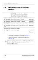
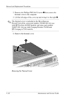
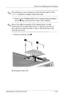
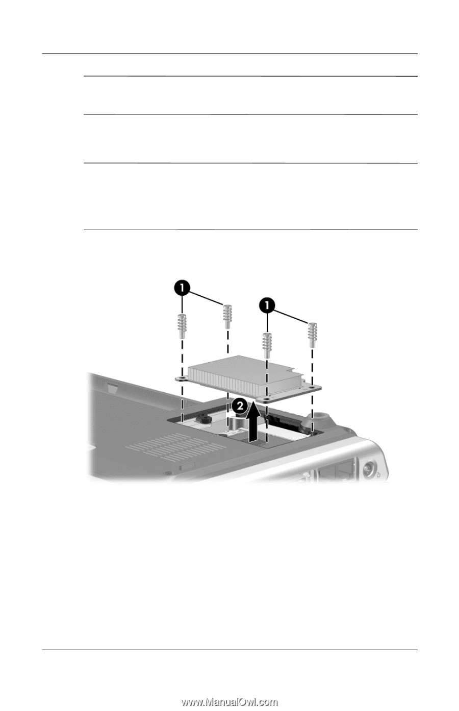
Removal and Replacement Procedures ✎ The following screws should be removed and installed in the 1, 2, 3, 4 sequence stamped on the heat sink. 5. Remove the 4 Phillips PM2.0×12.0 spring-loaded shoulder screws 1 that secure the heat sink to the computer. ✎ Due to the adhesive quality of the thermal paste located between the heat sink and processor, it may be necessary to move the heat sink from side to side to detach the heat sink from the processor. 6. Remove the heat sink 2. Removing the Heat Sink Maintenance and Service Guide 5-23
-
 1
1 -
2
-
3
-
4
-
5
-
6
-
7
-
8
-
9
-
10
-
11
-
12
-
13
-
14
-
15
-
16
-
17
-
18
-
19
-
20
-
21
-
22
-
23
-
24
-
25
-
26
-
27
-
28
-
29
-
30
-
31
-
32
-
33
-
34
-
35
-
36
-
37
-
38
-
39
-
40
-
41
-
42
-
43
-
44
-
45
-
46
-
47
-
48
-
49
-
50
-
51
-
52
-
53
-
54
-
55
-
56
-
57
-
58
-
59
-
60
-
61
-
62
-
63
-
64
-
65
-
66
-
67
-
68
-
69
-
70
-
71
-
72
-
73
-
74
-
75
-
76
-
77
-
78
-
79
-
80
-
81
-
82
-
83
-
84
-
85
-
86
-
87
-
88
-
89
-
90
-
91
-
92
-
93
-
94
-
95
-
96
-
97
-
98
-
99
-
100
-
101
-
102
-
103
-
104
-
105
-
106
-
107
-
108
-
109
-
110
-
111
-
112
-
113
-
114
-
115
-
116
-
117
-
118
-
119
-
120
-
121
-
122
-
123
-
 124
124 -
 125
125 -
 126
126 -
 127
127 -
 128
128 -
 129
129 -
 130
130 -
 131
131 -
 132
132 -
 133
133 -
 134
134 -
135
-
136
-
137
-
138
-
139
-
140
-
141
-
142
-
143
-
144
-
145
-
146
-
147
-
148
-
149
-
150
-
151
-
152
-
153
-
154
-
155
-
156
-
157
-
158
-
159
-
160
-
161
-
162
-
163
-
164
-
165
-
166
-
167
-
168
-
169
-
170
-
171
-
172
-
173
-
174
-
175
-
176
-
177
-
178
-
179
-
180
-
181
-
182
-
183
-
184
-
185
-
186
-
187
-
188
-
189
-
190
-
191
-
192
-
193
-
194
-
195
-
196
-
197
-
198
-
199
-
200
-
201
-
202
-
203
-
204
-
205
-
206
-
207
-
208
-
209
-
210
-
211
-
212
-
213
-
214
-
215
-
216
-
217
-
218
-
219
-
220
-
221
-
222
-
223
-
224
-
225
-
226
-
227
-
228
-
229
-
230
-
231
-
232
-
233
-
234
-
235
-
236
-
237
-
238
-
239
-
240
-
241
-
242
-
243
-
244
-
245
-
246
-
247
-
248
-
249
-
250
-
251
-
252
-
253
-
254
-
255
-
256
-
257
-
258
-
259
-
260
-
261
-
262
-
263
-
264
-
265
-
266
-
267
-
268
-
269
-
270
-
271
-
272
-
273
 |
 |
Removal and Replacement Procedures
Maintenance and Service Guide
5–23
✎
The following screws should be removed and installed in the
1, 2, 3, 4 sequence stamped on the heat sink.
5. Remove the 4 Phillips PM2.0×12.0 spring-loaded shoulder
screws
1
that secure the heat sink to the computer.
✎
Due to the adhesive quality of the thermal paste located
between the heat sink and processor, it may be necessary to
move the heat sink from side to side to detach the heat sink
from the processor.
6. Remove the heat sink
2
.
Removing the Heat Sink