HP Cisco MDS 9134 Cisco MDS 9200 Series Hardware Installation Guide (OL-16188- - Page 52
Power Supplies
 |
View all HP Cisco MDS 9134 manuals
Add to My Manuals
Save this manual to your list of manuals |
Page 52 highlights
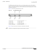
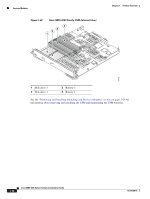
Power Supplies Chapter 1 Product Overview Power Supplies The Cisco MDS 9200 Series supports dual hot-swappable 845-W AC power supplies, each of which can supply sufficient power to the entire chassis should one power supply fail. The power supplies monitor their output voltage and provide status to the supervisor module. To prevent the unexpected shutdown of an optional module, power management software only allows a module to power up if adequate power is available. The Cisco MDS 9200 Series power supplies can be configured to be redundant or combined. By default, they are configured as redundant, so that if one fails, the remaining power supply can still power the entire system. For information on how to configure the power supplies, see the Cisco MDS 9000 Family CLI Configuration Guide or the Cisco MDS 9000 Family Fabric Manager Configuration Guide. The power supplies, which are accessed from the rear of the chassis, are illustrated in Figure 1-23. Figure 1-23 Cisco MDS 9200 Series with 845-W Dual Power Supplies 4 1 2 PWR-845-AC 100-240V 12-5A 50/60 Hz ALL FASTENERS MUST BE FULLY ENGAGED PRIOR TO OPERATING OF POWER SUPPLY 3 PWR-845-AC INPUT OK FAN OK OUTPUT FAIL 100-240V 12-5A 50/60 Hz ALL FASTENERS MUST BE FULLY ENGAGED PRIOR TO OPERATING OF POWER SUPPLY INPUT OK FAN OK OUTPUT FAIL 94002 1 Power supply switch 2 AC power connection 3 Power supply handle 4 Power supply LEDs Table 1-12 describes the LEDs for the Cisco MDS 9200 Series power supplies. Table 1-12 LEDs for the Cisco MDS 9200 Series Power Supplies LED Input OK Fan OK Output Fail Status Green Off Green Off Red Off Description AC input is good and power supply is functioning normally. Power supply is turned off or is not seated properly in the chassis. Power supply fans are operating properly. Fan is not operating or power supply is off. Power supply is not in a stable state. If this indication continues after initial power on, check that all connections are secure, including the system fan tray. Normal operation or power supply is turned off. 1-34 Cisco MDS 9200 Series Hardware Installation Guide OL-16188-01
-
 1
1 -
2
-
3
-
4
-
5
-
6
-
7
-
8
-
9
-
10
-
11
-
12
-
13
-
14
-
15
-
16
-
17
-
18
-
19
-
20
-
21
-
22
-
23
-
24
-
25
-
26
-
27
-
28
-
29
-
30
-
31
-
32
-
33
-
34
-
35
-
36
-
37
-
38
-
39
-
40
-
41
-
42
-
43
-
44
-
45
-
46
-
 47
47 -
 48
48 -
 49
49 -
 50
50 -
 51
51 -
 52
52 -
 53
53 -
 54
54 -
 55
55 -
 56
56 -
 57
57 -
58
-
59
-
60
-
61
-
62
-
63
-
64
-
65
-
66
-
67
-
68
-
69
-
70
-
71
-
72
-
73
-
74
-
75
-
76
-
77
-
78
-
79
-
80
-
81
-
82
-
83
-
84
-
85
-
86
-
87
-
88
-
89
-
90
-
91
-
92
-
93
-
94
-
95
-
96
-
97
-
98
-
99
-
100
-
101
-
102
-
103
-
104
-
105
-
106
-
107
-
108
-
109
-
110
-
111
-
112
-
113
-
114
-
115
-
116
-
117
-
118
-
119
-
120
-
121
-
122
-
123
-
124
-
125
-
126
-
127
-
128
-
129
-
130
-
131
-
132
-
133
-
134
-
135
-
136
-
137
-
138
-
139
-
140
-
141
-
142
-
143
-
144
-
145
-
146
-
147
-
148
-
149
-
150
-
151
-
152
-
153
-
154
-
155
-
156
-
157
-
158
-
159
-
160
-
161
-
162
-
163
-
164
 |
 |
