HP Cisco MDS 9216A HP StorageWorks C-Series iSCSI Configuration Guide (AA-RW7P - Page 42
Configuring p-Class Blade servers in an iSCSI environment
 |
View all HP Cisco MDS 9216A manuals
Add to My Manuals
Save this manual to your list of manuals |
Page 42 highlights
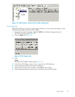
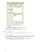
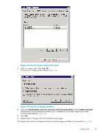
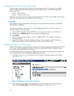
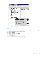
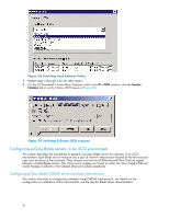
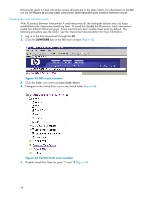
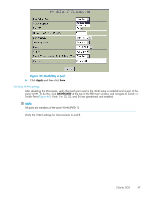
Figure 38 Selecting Load Balance Policy 7. Repeat steps 3 through 6 for the other target. 8. On the iSCSI-enabled C-Series Fibre Channel switch in the IP > iSCSI window, click the Session Initiators tab to verify C-Series iSCSI sessions (Figure 39). Figure 39 Verifying C-Series iSCSI sessions Configuring p-Class Blade servers in an iSCSI environment This section describes the procedures to prepare a p-Class Blade server for inclusion in an iSCSI environment. Each Blade server enclosure has a pair of network interconnects located at the left most and right most positions in the enclosure. They transmit and receive all Ethernet and Fibre Channel signals between installed Blade servers. The interconnect modules are based on either the Cisco Gigabit Ethernet Switch Module (CGESM) or the Gibabit Ethernet 2 (GbE2) standards. Configuring p-Class Blade CGESM server enclosure interconnects This section describes a configuration example using CGESM interconnects. For details on the configuration or installation of the interconnects, see the specific Blade server documentation. 42
-
 1
1 -
2
-
3
-
4
-
5
-
6
-
7
-
8
-
9
-
10
-
11
-
12
-
13
-
14
-
15
-
16
-
17
-
18
-
19
-
20
-
21
-
22
-
23
-
24
-
25
-
26
-
27
-
28
-
29
-
30
-
31
-
32
-
33
-
34
-
35
-
36
-
 37
37 -
 38
38 -
 39
39 -
 40
40 -
 41
41 -
 42
42 -
 43
43 -
 44
44 -
 45
45 -
 46
46 -
 47
47 -
48
-
49
 |
 |
