HP Cluster Platform Introduction v2010 HP Cluster Platform Server and Workstat - Page 113
Removing an HP ProLiant DL145 G3 from a Rack, Important Safety, Information
 |
View all HP Cluster Platform Introduction v2010 manuals
Add to My Manuals
Save this manual to your list of manuals |
Page 113 highlights
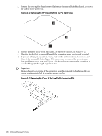
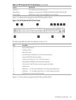
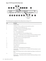
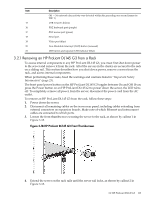
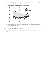
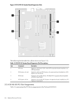
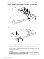
Item Description Off - No network data activity was detected within the preceding one second (same for NIC 1) 15 USB 2.0 ports (black) 16 PS/2 keyboard port (purple) 17 PS/2 mouse port (green) 18 Serial port 19 Video port (blue) 20 Non-Maskable Interrupt (NMI) button (recessed) 21 UID button and separate LED indicator (blue) 3.2.1 Removing an HP ProLiant DL145 G3 from a Rack To access internal components in any HP ProLiant DL145 G3, you must first shut down power to the server and remove it from the rack. All of the servers in the cluster are secured to the rack on a sliding rail. This section describes how you shut down power, remove a server from the rack, and access internal components. When performing these tasks, heed the warnings and cautions listed in "Important Safety Information" (page 23). The front panel power button on the HP ProLiant DL145 G3 toggles between On and Off. If you press the Power button on an HP ProLiant DL145 G3 to power down the server, the LED turns off. To completely remove all power from the server, disconnect the power cord from the AC outlet. To remove an HP ProLiant DL145 G3 from the rack, follow these steps: 1. Power down the server. 2. Disconnect all remaining cables on the server rear panel, including cables extending from external connectors on expansion boards. Make note of which Ethernet and interconnect cables are connected to which ports. 3. Loosen the front thumbscrews securing the server to the rack, as shown by callout 1 in Figure 3-18. Figure 3-18 HP ProLiant DL145 G3 Front Thumbscrews 1 2 4. Extend the server on the rack rails until the server rail locks, as shown by callout 2 in Figure 3-18. 3.2 HP ProLiant DL145 G3 113
-
 1
1 -
2
-
3
-
4
-
5
-
6
-
7
-
8
-
9
-
10
-
11
-
12
-
13
-
14
-
15
-
16
-
17
-
18
-
19
-
20
-
21
-
22
-
23
-
24
-
25
-
26
-
27
-
28
-
29
-
30
-
31
-
32
-
33
-
34
-
35
-
36
-
37
-
38
-
39
-
40
-
41
-
42
-
43
-
44
-
45
-
46
-
47
-
48
-
49
-
50
-
51
-
52
-
53
-
54
-
55
-
56
-
57
-
58
-
59
-
60
-
61
-
62
-
63
-
64
-
65
-
66
-
67
-
68
-
69
-
70
-
71
-
72
-
73
-
74
-
75
-
76
-
77
-
78
-
79
-
80
-
81
-
82
-
83
-
84
-
85
-
86
-
87
-
88
-
89
-
90
-
91
-
92
-
93
-
94
-
95
-
96
-
97
-
98
-
99
-
100
-
101
-
102
-
103
-
104
-
105
-
106
-
107
-
 108
108 -
 109
109 -
 110
110 -
 111
111 -
 112
112 -
 113
113 -
 114
114 -
 115
115 -
 116
116 -
 117
117 -
 118
118 -
119
-
120
-
121
-
122
-
123
-
124
-
125
-
126
-
127
-
128
-
129
-
130
-
131
-
132
-
133
-
134
-
135
-
136
-
137
-
138
-
139
-
140
-
141
-
142
-
143
-
144
-
145
-
146
-
147
-
148
-
149
-
150
-
151
-
152
-
153
-
154
-
155
-
156
-
157
-
158
-
159
-
160
-
161
-
162
-
163
-
164
-
165
-
166
-
167
-
168
-
169
-
170
-
171
-
172
-
173
-
174
-
175
-
176
-
177
-
178
-
179
-
180
-
181
-
182
-
183
-
184
-
185
-
186
-
187
-
188
-
189
-
190
-
191
-
192
-
193
-
194
-
195
-
196
-
197
-
198
-
199
-
200
-
201
-
202
-
203
-
204
-
205
-
206
-
207
-
208
-
209
-
210
-
211
-
212
-
213
-
214
-
215
-
216
-
217
-
218
-
219
-
220
-
221
-
222
-
223
-
224
-
225
-
226
-
227
-
228
-
229
-
230
-
231
-
232
-
233
-
234
-
235
-
236
-
237
-
238
-
239
-
240
-
241
-
242
-
243
-
244
-
245
-
246
-
247
-
248
 |
 |