HP Dx5150 HP Business Desktop dx5150 Series Service Reference Guide, 1st Editi - Page 81
Front I/O Panel Housing Assembly
 |
UPC - 882780485433
View all HP Dx5150 manuals
Add to My Manuals
Save this manual to your list of manuals |
Page 81 highlights
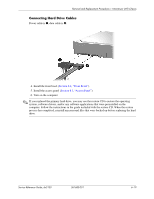
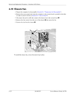
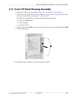
Removal and Replacement Procedures- Microtower (MT) Chassis 6.11 Front I/O Panel Housing Assembly 1. Prepare the computer for disassembly (Section 6.1, "Preparation for Disassembly"). 2. Remove the access panel and rotate the computer so the system board is parallel to the table to make it easier to work on (Section 6.3, "Access Panel"). 3. Disconnect the following three attaching cables from the system board: ❏ power switch/LED cable ❏ front USB cable ❏ front audio cable 4. Remove the two screws 1 that secure the housing to the chassis and then pull the housing 2 away from the chassis. To install the housing assembly, reverse the removal procedures. Service Reference Guide, dx5150 361685-001 6-21
-
 1
1 -
2
-
3
-
4
-
5
-
6
-
7
-
8
-
9
-
10
-
11
-
12
-
13
-
14
-
15
-
16
-
17
-
18
-
19
-
20
-
21
-
22
-
23
-
24
-
25
-
26
-
27
-
28
-
29
-
30
-
31
-
32
-
33
-
34
-
35
-
36
-
37
-
38
-
39
-
40
-
41
-
42
-
43
-
44
-
45
-
46
-
47
-
48
-
49
-
50
-
51
-
52
-
53
-
54
-
55
-
56
-
57
-
58
-
59
-
60
-
61
-
62
-
63
-
64
-
65
-
66
-
67
-
68
-
69
-
70
-
71
-
72
-
73
-
74
-
75
-
 76
76 -
 77
77 -
 78
78 -
 79
79 -
 80
80 -
 81
81 -
 82
82 -
 83
83 -
 84
84 -
 85
85 -
 86
86 -
87
-
88
-
89
-
90
-
91
-
92
-
93
-
94
-
95
-
96
-
97
-
98
-
99
-
100
-
101
-
102
-
103
-
104
-
105
-
106
-
107
-
108
-
109
-
110
-
111
-
112
-
113
-
114
-
115
-
116
-
117
-
118
-
119
-
120
-
121
-
122
-
123
-
124
-
125
-
126
-
127
-
128
-
129
-
130
-
131
-
132
-
133
-
134
-
135
-
136
-
137
-
138
-
139
-
140
-
141
-
142
-
143
-
144
-
145
-
146
-
147
-
148
-
149
-
150
-
151
-
152
-
153
-
154
-
155
-
156
-
157
-
158
-
159
-
160
-
161
-
162
-
163
-
164
-
165
-
166
-
167
-
168
-
169
-
170
-
171
-
172
-
173
-
174
-
175
-
176
-
177
-
178
-
179
-
180
-
181
-
182
 |
 |

Service Reference Guide, dx5150
361685-001
6–21
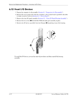
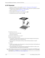
Removal and Replacement Procedures— Microtower (MT) Chassis
6.11 Front I/O Panel Housing Assembly
1. Prepare the computer for disassembly (
Section 6.1, “Preparation for Disassembly”
).
2. Remove the access panel and rotate the computer so the system board is parallel to the table
to make it easier to work on (
Section 6.3, “Access Panel”
).
3. Disconnect the following three attaching cables from the system board:
❏
power switch/LED cable
❏
front USB cable
❏
front audio cable
4. Remove the two screws
1
that secure the housing to the chassis and then pull the housing
2
away from the chassis.
To install the housing assembly, reverse the removal procedures.