HP Dx5150 HP Business Desktop dx5150 Series Service Reference Guide, 1st Editi - Page 87
System Board
 |
UPC - 882780485433
View all HP Dx5150 manuals
Add to My Manuals
Save this manual to your list of manuals |
Page 87 highlights
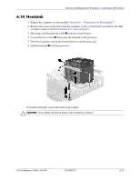
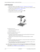
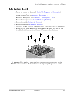
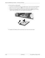
Removal and Replacement Procedures- Microtower (MT) Chassis 6.16 System Board 1. Prepare the computer for disassembly (Section 6.1, "Preparation for Disassembly"). 2. Remove the access panel and rotate the computer so the system board is parallel to the table to make it easier to work on (Section 6.3, "Access Panel"). 3. Remove all PCI expansion cards (Section 6.8.2, "PCI Expansion Card"). 4. Remove the memory modules (Section 6.7, "Memory Modules"). 5. Remove the heatsink (Section 6.14, "Heatsink"). 6. Remove the processor (Section 6.15, "Processor"). 7. Disconnect all cables connected to the system board, noting their location for reinstallation. 8. Remove the eight screws that secure the system board to the chassis, then slide the board toward the front of the computer until the rear I/O connectors clear the chassis. Ä CAUTION: When installing a new system board, you must attach a new processor backing plate to the system board. The heatsink will not attach properly if this plate is not installed. Service Reference Guide, dx5150 361685-001 6-27
-
 1
1 -
2
-
3
-
4
-
5
-
6
-
7
-
8
-
9
-
10
-
11
-
12
-
13
-
14
-
15
-
16
-
17
-
18
-
19
-
20
-
21
-
22
-
23
-
24
-
25
-
26
-
27
-
28
-
29
-
30
-
31
-
32
-
33
-
34
-
35
-
36
-
37
-
38
-
39
-
40
-
41
-
42
-
43
-
44
-
45
-
46
-
47
-
48
-
49
-
50
-
51
-
52
-
53
-
54
-
55
-
56
-
57
-
58
-
59
-
60
-
61
-
62
-
63
-
64
-
65
-
66
-
67
-
68
-
69
-
70
-
71
-
72
-
73
-
74
-
75
-
76
-
77
-
78
-
79
-
80
-
81
-
 82
82 -
 83
83 -
 84
84 -
 85
85 -
 86
86 -
 87
87 -
 88
88 -
 89
89 -
 90
90 -
 91
91 -
 92
92 -
93
-
94
-
95
-
96
-
97
-
98
-
99
-
100
-
101
-
102
-
103
-
104
-
105
-
106
-
107
-
108
-
109
-
110
-
111
-
112
-
113
-
114
-
115
-
116
-
117
-
118
-
119
-
120
-
121
-
122
-
123
-
124
-
125
-
126
-
127
-
128
-
129
-
130
-
131
-
132
-
133
-
134
-
135
-
136
-
137
-
138
-
139
-
140
-
141
-
142
-
143
-
144
-
145
-
146
-
147
-
148
-
149
-
150
-
151
-
152
-
153
-
154
-
155
-
156
-
157
-
158
-
159
-
160
-
161
-
162
-
163
-
164
-
165
-
166
-
167
-
168
-
169
-
170
-
171
-
172
-
173
-
174
-
175
-
176
-
177
-
178
-
179
-
180
-
181
-
182
 |
 |
