HP Integrity Superdome 2 16-socket Cisco Nexus B22 Fabric Extender for HP Gett - Page 4
Rear View of the Enclosure, Cisco Nexus B22 Fabric Extender for HP Getting Started Guide
 |
View all HP Integrity Superdome 2 16-socket manuals
Add to My Manuals
Save this manual to your list of manuals |
Page 4 highlights
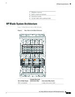
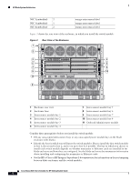
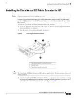
HP Blade System Architecture NIC 2(embedded) 2 NIC 3(embedded) 1 NIC 4(embedded) 2 orange interconnect label orange interconnect label orange interconnect label Figure 3 shows the rear view of the enclosure, in which you install the switch module. Figure 3 1 2 Rear View of the Enclosure 3 4 5 6 7 8 9 10 11 2 153140 1 Enclosure rear view 2 Enclosure fans 3 Interconnect module bay 1 4 Interconnect module bay 2 5 Interconnect module bay 3 6 Interconnect module bay 4 7 Interconnect module bay 5 8 Interconnect module bay 6 9 Interconnect module bay 7 10 Interconnect module bay 8 11 Onboard Administrator module Consider these prerequisites before you install the switch module: • Fill any unoccupied interconnect bays or any unoccupied power module bays in the blade enclosure with blanks. • Identify the bays in which you will insert the switch modules. Plan to install the first switch module in bay 1, the second in bay 2, and so on up to bay 8, if possible. The bay in which you choose to install each switch module depends on whether mezzanine or Ethernet cards are installed in the blade enclosure and how they are configured. See the blade enclosure documentation information about installing and configuring the mezzanine or Ethernet cards. • See the HP c-Class or HP Integrity Superdome 2 documentation for information on the port mapping between blade enclosures and the switch modules. Cisco Nexus B22 Fabric Extender for HP Getting Started Guide 4
-
 1
1 -
 2
2 -
 3
3 -
 4
4 -
 5
5 -
 6
6 -
 7
7 -
 8
8 -
 9
9 -
 10
10 -
11
-
12
-
13
-
14
-
15
-
16
-
17
-
18
-
19
-
20
-
21
-
22
 |
 |
