HP Integrity Superdome SX2000 User Guide, Sixth Edition - HP Integrity Superdo - Page 105
Installing the PDCA, Step 5.
 |
View all HP Integrity Superdome SX2000 manuals
Add to My Manuals
Save this manual to your list of manuals |
Page 105 highlights
Removing and Replacing Components Installing An Additional Power Distribution Control Assembly 1. Run the power cord down through the appropriate opening in the floor tile. 2. Partially insert the PDCA into its slot. 3. Slip the L bracket under the power cord on the rear of the PDCA. 4. While holding the L bracket in place, insert the PDCA completely into the cabinet and secure the L bracket with one screw. Figure 3-8 Installing the PDCA 5. Using a T20 Torx driver, attach the four screws that hold the PDCA in place. Step 5. Plug the power cord into the AC power source. Step 6. Power on the AC supply to the server. Step 7. Power on and boot up the server. Chapter 3 93
-
 1
1 -
2
-
3
-
4
-
5
-
6
-
7
-
8
-
9
-
10
-
11
-
12
-
13
-
14
-
15
-
16
-
17
-
18
-
19
-
20
-
21
-
22
-
23
-
24
-
25
-
26
-
27
-
28
-
29
-
30
-
31
-
32
-
33
-
34
-
35
-
36
-
37
-
38
-
39
-
40
-
41
-
42
-
43
-
44
-
45
-
46
-
47
-
48
-
49
-
50
-
51
-
52
-
53
-
54
-
55
-
56
-
57
-
58
-
59
-
60
-
61
-
62
-
63
-
64
-
65
-
66
-
67
-
68
-
69
-
70
-
71
-
72
-
73
-
74
-
75
-
76
-
77
-
78
-
79
-
80
-
81
-
82
-
83
-
84
-
85
-
86
-
87
-
88
-
89
-
90
-
91
-
92
-
93
-
94
-
95
-
96
-
97
-
98
-
99
-
 100
100 -
 101
101 -
 102
102 -
 103
103 -
 104
104 -
 105
105 -
 106
106 -
 107
107 -
 108
108 -
 109
109 -
 110
110 -
111
-
112
-
113
-
114
-
115
-
116
-
117
-
118
-
119
-
120
-
121
-
122
-
123
-
124
-
125
-
126
-
127
-
128
-
129
-
130
-
131
-
132
-
133
-
134
-
135
-
136
-
137
-
138
-
139
-
140
-
141
-
142
-
143
-
144
-
145
-
146
-
147
-
148
-
149
-
150
-
151
-
152
-
153
-
154
-
155
-
156
-
157
-
158
-
159
-
160
-
161
-
162
-
163
-
164
-
165
-
166
-
167
-
168
-
169
-
170
-
171
-
172
-
173
-
174
-
175
-
176
-
177
-
178
-
179
-
180
-
181
-
182
-
183
-
184
-
185
-
186
-
187
-
188
-
189
-
190
-
191
-
192
-
193
-
194
-
195
-
196
-
197
-
198
-
199
-
200
-
201
-
202
-
203
-
204
-
205
-
206
-
207
-
208
-
209
-
210
-
211
-
212
-
213
-
214
-
215
-
216
-
217
-
218
-
219
-
220
-
221
-
222
-
223
-
224
-
225
-
226
-
227
-
228
-
229
-
230
-
231
-
232
-
233
-
234
-
235
-
236
-
237
-
238
-
239
-
240
-
241
-
242
-
243
-
244
-
245
-
246
-
247
-
248
-
249
-
250
-
251
-
252
-
253
-
254
-
255
-
256
-
257
-
258
-
259
-
260
-
261
-
262
-
263
-
264
-
265
-
266
-
267
-
268
-
269
-
270
-
271
-
272
-
273
-
274
-
275
-
276
-
277
-
278
-
279
-
280
-
281
-
282
-
283
-
284
-
285
-
286
-
287
-
288
-
289
-
290
-
291
-
292
-
293
-
294
-
295
-
296
-
297
-
298
-
299
-
300
-
301
-
302
-
303
-
304
-
305
-
306
-
307
-
308
-
309
-
310
-
311
-
312
-
313
-
314
-
315
-
316
-
317
-
318
-
319
-
320
-
321
-
322
-
323
-
324
-
325
-
326
-
327
-
328
-
329
-
330
-
331
-
332
 |
 |

Chapter 3
Removing and Replacing Components
Installing An Additional Power Distribution Control Assembly
93
1. Run the power cord down through the appropriate opening in the floor tile.
2. Partially insert the PDCA into its slot.
3. Slip the L bracket under the power cord on the rear of the PDCA.
4. While holding the L bracket in place, insert the PDCA completely into the cabinet and secure
the L bracket with one screw.
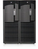
Figure 3-8 Installing the PDCA
5. Using a T20 Torx driver, attach the four screws that hold the PDCA in place.
Step 5.
Plug the power cord into the AC power source.
Step 6.
Power on the AC supply to the server.
Step 7.
Power on and boot up the server.