HP Integrity rx1620 Internal Cabling Guide for HP Smart Array Controllers - Page 55
Setting up RAID Cabling for Dual Partitions, Step 1., LAN/SCSI card.
 |
View all HP Integrity rx1620 manuals
Add to My Manuals
Save this manual to your list of manuals |
Page 55 highlights
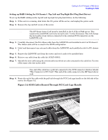
Cabling for the HP Integrity rx7640 Server Recabling for RAID Setting up RAID Cabling for Dual Partitions To set up the RAID cabling do the following: Step 1. If the server is running, shut down the OS, power off the server, and unplug the power cords. Step 2. Remove the top and left covers of the server. NOTE The HP Smart Array Cards must be installed in slot 8 of the rx7640 server. This requires the LAN/SCSI cards to be moved to slot 7 in the IO chassis. This will change the boot paths of any devices connected to the external SCSI connectors on the LAN/SCSI card. Step 3. Carefully disconnect the flat ribbon cable from the LAN/SCSI card installed in slot 8 of IO chassis 0. The ribbon cable will be re-used in the RAID configuration. Step 4. Label and dissconnect any external cables from the LAN/SCSI card installed in slot 8 of IO chassis 0. Step 5. Label and remove the LAN/SCSI card from the server and set it aside to be installed later. Step 6. Carefully disconnect the flat ribbon cable from the LAN/SCSI card installed in slot 8 of IO chassi 1. The ribbon cable will be re-used in the RAID configuration. Step 7. Label and dissconnect any external cables from the LAN/SCSI card installed in slot 8 of IO chassis 1. Step 8. Label and remove the LAN/SCSI card from the server and set it aside to be installed later. Step 9. Retrieve two cables from the cable kit (A7027-63001). Step 10. Identify the new cables using the colored cable ties which are also contained in the cable kit. Use two of the same color ties on each cable. NOTE One end of each cable has a pull-tab connected to the SCSI connector which is labeled "This Connector to PCI Card". This end of the cable connects to the HP Smart Array card. Step 11. Route the end of the cables with the pull-tab through the PCI Card cage handle on the left side of the server. See Figure 5-7. Chapter 5 51
-
 1
1 -
2
-
3
-
4
-
5
-
6
-
7
-
8
-
9
-
10
-
11
-
12
-
13
-
14
-
15
-
16
-
17
-
18
-
19
-
20
-
21
-
22
-
23
-
24
-
25
-
26
-
27
-
28
-
29
-
30
-
31
-
32
-
33
-
34
-
35
-
36
-
37
-
38
-
39
-
40
-
41
-
42
-
43
-
44
-
45
-
46
-
47
-
48
-
49
-
 50
50 -
 51
51 -
 52
52 -
 53
53 -
 54
54 -
 55
55 -
 56
56 -
 57
57 -
 58
58 -
 59
59 -
 60
60 -
61
-
62
-
63
-
64
-
65
-
66
-
67
-
68
-
69
-
70
-
71
-
72
-
73
-
74
-
75
-
76
-
77
-
78
-
79
-
80
-
81
-
82
-
83
-
84
-
85
-
86
-
87
-
88
-
89
-
90
-
91
-
92
-
93
-
94
-
95
-
96
 |
 |
