HP Mini 1000 HP Mini 1000 NetBook - Maintenance and Service Guide - Page 53
that secure the actuators for the power switch, was disconnected earlier see
 |
View all HP Mini 1000 manuals
Add to My Manuals
Save this manual to your list of manuals |
Page 53 highlights
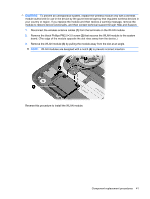
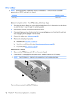
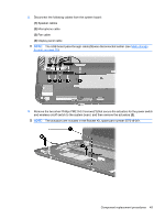
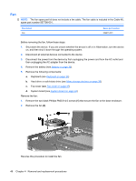
2. Disconnect the following cables from the system board: (1) Speaker cables (2) Microphone cable (3) Fan cable (4) Display panel cable NOTE: The USB board pass-through cable (5) was disconnected earlier (see Mass storage devices on page 35). 3. Remove the two silver Phillips PM2.0×3.0 screws (1) that secure the actuators for the power switch and wireless on/off switch to the system board, and then remove the actuators (2). NOTE: The actuators are included in the Bracket Kit, spare part number 507318-001. Component replacement procedures 45
-
 1
1 -
2
-
3
-
4
-
5
-
6
-
7
-
8
-
9
-
10
-
11
-
12
-
13
-
14
-
15
-
16
-
17
-
18
-
19
-
20
-
21
-
22
-
23
-
24
-
25
-
26
-
27
-
28
-
29
-
30
-
31
-
32
-
33
-
34
-
35
-
36
-
37
-
38
-
39
-
40
-
41
-
42
-
43
-
44
-
45
-
46
-
47
-
 48
48 -
 49
49 -
 50
50 -
 51
51 -
 52
52 -
 53
53 -
 54
54 -
 55
55 -
 56
56 -
 57
57 -
 58
58 -
59
-
60
-
61
-
62
-
63
-
64
-
65
-
66
-
67
-
68
-
69
-
70
-
71
-
72
-
73
-
74
-
75
-
76
-
77
-
78
-
79
-
80
-
81
-
82
-
83
-
84
-
85
-
86
-
87
-
88
-
89
-
90
-
91
-
92
-
93
-
94
-
95
-
96
-
97
-
98
-
99
-
100
-
101
-
102
-
103
-
104
-
105
 |
 |

2.
Disconnect the following cables from the system board:
(1)
Speaker cables
(2)
Microphone cable
(3)
Fan cable
(4)
Display panel cable
NOTE:
The USB board pass-through cable
(5)
was disconnected earlier (see
Mass storage
devices
on page
35
).
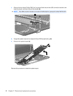
3.
Remove the two silver Phillips PM2.0×3.0 screws
(1)
that secure the actuators for the power switch
and wireless on/off switch to the system board, and then remove the actuators
(2)
.
NOTE:
The actuators are included in the Bracket Kit, spare part number 507318-001.
Component replacement procedures
45