HP Presario CQ61-100 Compaq Presario CQ61 Notebook PC and HP G61 Notebook PC - - Page 58
Remove the Phillips PM2.0×3.0 screw, that secures the WLAN module to the computer. The edge of - restore
 |
View all HP Presario CQ61-100 manuals
Add to My Manuals
Save this manual to your list of manuals |
Page 58 highlights
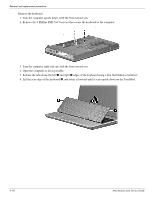
Removal and replacement procedures Remove the wireless module: Ä CAUTION: To prevent an unresponsive system, replace the wireless module only with a wireless module authorized for use in the computer by the governmental agency that regulates wireless devices in your country or region. If you replace the module and then receive a warning message, remove the module to restore computer functionality, and then contact technical support through Help and Support. 1. Loosen the Phillips PM2.5×6.0 captive screw 1 that secures the wireless compartment cover to the computer. 2. Lift the right side of the cover 2, swing it to the left, and lift up to remove it 3. The wireless compartment cover is included in the Plastics Kit, spare part number 531517-001. 3. Disconnect the main antenna cable 1 and the auxiliary antenna cable 2 from the wireless module. ✎ The black WLAN antenna cable (marked "1") is connected to the WLAN module "Main" terminal. The white WLAN antenna cable (marked "2") is connected to the WLAN module "Aux" terminal. 4. Remove the Phillips PM2.0×3.0 screw 3 that secures the WLAN module to the computer. (The edge of the module opposite the slot rises away from the computer.) 5. Remove the WLAN module 4 by pulling the module away from the slot at an angle. ✎ WLAN modules are designed with a notch 5 to prevent incorrect insertion. Reverse this procedure to install the wireless module. Maintenance and Service Guide 4-15
-
 1
1 -
2
-
3
-
4
-
5
-
6
-
7
-
8
-
9
-
10
-
11
-
12
-
13
-
14
-
15
-
16
-
17
-
18
-
19
-
20
-
21
-
22
-
23
-
24
-
25
-
26
-
27
-
28
-
29
-
30
-
31
-
32
-
33
-
34
-
35
-
36
-
37
-
38
-
39
-
40
-
41
-
42
-
43
-
44
-
45
-
46
-
47
-
48
-
49
-
50
-
51
-
52
-
 53
53 -
 54
54 -
 55
55 -
 56
56 -
 57
57 -
 58
58 -
 59
59 -
 60
60 -
 61
61 -
 62
62 -
 63
63 -
64
-
65
-
66
-
67
-
68
-
69
-
70
-
71
-
72
-
73
-
74
-
75
-
76
-
77
-
78
-
79
-
80
-
81
-
82
-
83
-
84
-
85
-
86
-
87
-
88
-
89
-
90
-
91
-
92
-
93
-
94
-
95
-
96
-
97
-
98
-
99
-
100
-
101
-
102
-
103
-
104
-
105
-
106
-
107
-
108
-
109
-
110
-
111
-
112
-
113
-
114
-
115
-
116
-
117
-
118
-
119
-
120
-
121
-
122
-
123
-
124
-
125
-
126
-
127
-
128
-
129
-
130
-
131
-
132
-
133
-
134
-
135
-
136
-
137
 |
 |
