HP Presario CQ61-100 Compaq Presario CQ61 Notebook PC and HP G61 Notebook PC - - Page 68
Remove the 4 Phillips PM2.5×7.0 screws, following screw covers and screws
 |
View all HP Presario CQ61-100 manuals
Add to My Manuals
Save this manual to your list of manuals |
Page 68 highlights
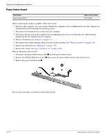
Removal and replacement procedures Ä CAUTION: Support the display assembly when removing the following screws. Failure to support the display assembly can result in damage to the display assembly and other computer components. 5. Remove the 4 Phillips PM2.5×7.0 screws 1 securing the display hinges to the computer. 6. Lift the display panel 2 straight up to remove it. 7. If it is necessary to replace the display bezel or any of the display assembly internal components, remove the following screw covers and screws: 1 Two rubber screw covers on the display bezel bottom edge. The display rubber screw covers are included in the Display Rubber Kit, spare part number 530999-001. 2 Two Phillips PM2.5×7.0 screws on the display bezel bottom edge. Maintenance and Service Guide 4-25
-
 1
1 -
2
-
3
-
4
-
5
-
6
-
7
-
8
-
9
-
10
-
11
-
12
-
13
-
14
-
15
-
16
-
17
-
18
-
19
-
20
-
21
-
22
-
23
-
24
-
25
-
26
-
27
-
28
-
29
-
30
-
31
-
32
-
33
-
34
-
35
-
36
-
37
-
38
-
39
-
40
-
41
-
42
-
43
-
44
-
45
-
46
-
47
-
48
-
49
-
50
-
51
-
52
-
53
-
54
-
55
-
56
-
57
-
58
-
59
-
60
-
61
-
62
-
 63
63 -
 64
64 -
 65
65 -
 66
66 -
 67
67 -
 68
68 -
 69
69 -
 70
70 -
 71
71 -
 72
72 -
 73
73 -
74
-
75
-
76
-
77
-
78
-
79
-
80
-
81
-
82
-
83
-
84
-
85
-
86
-
87
-
88
-
89
-
90
-
91
-
92
-
93
-
94
-
95
-
96
-
97
-
98
-
99
-
100
-
101
-
102
-
103
-
104
-
105
-
106
-
107
-
108
-
109
-
110
-
111
-
112
-
113
-
114
-
115
-
116
-
117
-
118
-
119
-
120
-
121
-
122
-
123
-
124
-
125
-
126
-
127
-
128
-
129
-
130
-
131
-
132
-
133
-
134
-
135
-
136
-
137
 |
 |
