HP Presario CQ61-100 Compaq Presario CQ61 Notebook PC and HP G61 Notebook PC - - Page 63
Switch cover, 6 Phillips PM2.5×7.0 screws
 |
View all HP Presario CQ61-100 manuals
Add to My Manuals
Save this manual to your list of manuals |
Page 63 highlights
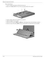
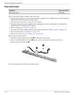
Removal and replacement procedures Switch cover Description Switch cover Spare part number 531207-001 Before removing the switch cover, follow these steps: 1. Shut down the computer. If you are unsure whether the computer is off or in Hibernation, turn the computer on, and then shut it down through the operating system. 2. Disconnect all external devices connected to the computer. 3. Disconnect the power from the computer by first unplugging the power cord from the AC outlet and then unplugging the AC adapter from the computer. 4. Remove the battery ("Battery" on page 4-7). 5. Remove the hard drive ("Hard drive" on page 4-10). 6. Remove the wireless module ("Wireless module" on page 4-14). 7. Remove the keyboard ("Keyboard" on page 4-17). Remove the switch cover: 1. In the battery bay, remove the 2 Phillips PM 2.5×8.0 screws 1, 6 Phillips PM2.5×7.0 screws 2, and the 5 Phillips PM2.5×5.0 screws 3 that secure the cover to the computer. The switch cover screws are identified by a triangle icon embossed on the base enclosure. 2. Turn the computer right-side up, with the front toward you. 3. Open the computer as far as possible. 4-20 Maintenance and Service Guide
-
 1
1 -
2
-
3
-
4
-
5
-
6
-
7
-
8
-
9
-
10
-
11
-
12
-
13
-
14
-
15
-
16
-
17
-
18
-
19
-
20
-
21
-
22
-
23
-
24
-
25
-
26
-
27
-
28
-
29
-
30
-
31
-
32
-
33
-
34
-
35
-
36
-
37
-
38
-
39
-
40
-
41
-
42
-
43
-
44
-
45
-
46
-
47
-
48
-
49
-
50
-
51
-
52
-
53
-
54
-
55
-
56
-
57
-
 58
58 -
 59
59 -
 60
60 -
 61
61 -
 62
62 -
 63
63 -
 64
64 -
 65
65 -
 66
66 -
 67
67 -
 68
68 -
69
-
70
-
71
-
72
-
73
-
74
-
75
-
76
-
77
-
78
-
79
-
80
-
81
-
82
-
83
-
84
-
85
-
86
-
87
-
88
-
89
-
90
-
91
-
92
-
93
-
94
-
95
-
96
-
97
-
98
-
99
-
100
-
101
-
102
-
103
-
104
-
105
-
106
-
107
-
108
-
109
-
110
-
111
-
112
-
113
-
114
-
115
-
116
-
117
-
118
-
119
-
120
-
121
-
122
-
123
-
124
-
125
-
126
-
127
-
128
-
129
-
130
-
131
-
132
-
133
-
134
-
135
-
136
-
137
 |
 |
