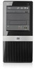
HP Pro 3000 Hardware Reference Guide - HP Pro 2000 and 3000 Series Microtower
HP Pro 3000 - Microtower PC Manual
 |
View all HP Pro 3000 manuals
Add to My Manuals
Save this manual to your list of manuals |
HP Pro 3000 manual content summary:
- HP Pro 3000 | Hardware Reference Guide - HP Pro 2000 and 3000 Series Microtower - Page 1
Hardware Reference Guide HP Pro 2000 and 3000 Series Microtower Business PCs - HP Pro 3000 | Hardware Reference Guide - HP Pro 2000 and 3000 Series Microtower - Page 2
HP products and services are set forth in the express warranty statements accompanying such products and services. Nothing herein should be construed as constituting an additional warranty. HP . Hardware Reference Guide HP Pro 2000 and 3000 Series Microtower Business PCs Second Edition (October - HP Pro 3000 | Hardware Reference Guide - HP Pro 2000 and 3000 Series Microtower - Page 3
provides basic information for upgrading these computer models. The model illustrated in this guide may look different than your computer model. WARNING! Text set off in this manner indicates that failure to follow directions could result in bodily harm - HP Pro 3000 | Hardware Reference Guide - HP Pro 2000 and 3000 Series Microtower - Page 4
iv About This Book - HP Pro 3000 | Hardware Reference Guide - HP Pro 2000 and 3000 Series Microtower - Page 5
Drive 23 Battery Replacement ...26 Installing a Security Lock ...28 HP/Kensington MicroSaver Security Cable Lock 29 Padlock ...29 HP Business PC Security Lock 30 Hood Sensor ...32 Port Cover ...33 HP Chassis Security Kit ...34 Appendix A Electrostatic Discharge Preventing Electrostatic Damage - HP Pro 3000 | Hardware Reference Guide - HP Pro 2000 and 3000 Series Microtower - Page 6
Cleaning ...37 Safety ...37 Shipping Preparation ...37 Index ...38 vi - HP Pro 3000 | Hardware Reference Guide - HP Pro 2000 and 3000 Series Microtower - Page 7
read all of the applicable instructions, cautions, and warnings in this guide. WARNING! To reduce the risk mechanical safety information. This guide is located on the Web at http://www.hp.com/ergo. WARNING! Setup utility, and troubleshooting, refer to the Maintenance and Service Guide (available in - HP Pro 3000 | Hardware Reference Guide - HP Pro 2000 and 3000 Series Microtower - Page 8
Removing the Computer Access Panel 1. Remove/disengage any security devices that prohibit opening the computer. 2. Remove all removable media, such as compact discs or USB flash drives, from the computer. 3. Turn off the computer properly through the operating system, then turn off any external - HP Pro 3000 | Hardware Reference Guide - HP Pro 2000 and 3000 Series Microtower - Page 9
Replacing the Computer Access Panel Place the access panel on the chassis with about 1.3 cm (1/2 inch) of the panel hanging off the back of the chassis and slide it into place (1). Ensure that the hole for the screw is aligned with the hole in the chassis and tighten the screw (2). Figure 2 - HP Pro 3000 | Hardware Reference Guide - HP Pro 2000 and 3000 Series Microtower - Page 10
from the front bezel (1), then discard the bezel blank. If the blank needs to be replaced at a later date, you can order a replacement blank from HP. 4 Hardware Upgrades - HP Pro 3000 | Hardware Reference Guide - HP Pro 2000 and 3000 Series Microtower - Page 11
3. To remove the 3.5-inch bezel blank, press the two retaining tabs towards the outer left edge of the bezel (2) and pull the bezel blank inwards to free it from the front bezel (3). Figure 4 Removing a Bezel Blank 4. Replace the front bezel. Replacing the Front Bezel Insert the three hooks on the - HP Pro 3000 | Hardware Reference Guide - HP Pro 2000 and 3000 Series Microtower - Page 12
sockets are populated with at least one preinstalled DIMM. To achieve the maximum memory support, you can populate the system board with up to 4GB of memory on HP Pro 2000 series models or 8GB of memory on HP Pro 3000 series models. DDR3-SDRAM DIMMs For proper system operation, the DDR3-SDRAM DIMMs - HP Pro 3000 | Hardware Reference Guide - HP Pro 2000 and 3000 Series Microtower - Page 13
of the memory module socket (1), and insert the memory module into the socket (2). NOTE: On HP Pro 2000 systems, populate the DIMM sockets in the following order: DIMM1 then DIMM2. On HP Pro 3000 systems with Intel processors, populate the DIMM sockets in the following order: DIMM1, DIMM3, DIMM2 - HP Pro 3000 | Hardware Reference Guide - HP Pro 2000 and 3000 Series Microtower - Page 14
11. Reconnect the power cord and any external devices, then turn on the computer. The computer should automatically recognize the additional memory when you turn on the computer. 12. Lock any security devices that were disengaged when the access panel was removed. 8 Hardware Upgrades - HP Pro 3000 | Hardware Reference Guide - HP Pro 2000 and 3000 Series Microtower - Page 15
Removing or Installing an Expansion Card Depending on the model, the computer may include PCI Express x1 expansion slots, PCI Express x16 expansion slots, and standard PCI expansion slots. NOTE: You can install a PCI Express x1, x4, x8, or x16 expansion card in the PCI Express x16 expansion slot. To - HP Pro 3000 | Hardware Reference Guide - HP Pro 2000 and 3000 Series Microtower - Page 16
NOTE: Before removing an installed expansion card, disconnect any cables that may be attached to the expansion card. a. If you are installing an expansion card in a vacant socket, you must use a flatblade screwdriver to pry out the metal shield on the rear panel that covers the expansion slot. Be - HP Pro 3000 | Hardware Reference Guide - HP Pro 2000 and 3000 Series Microtower - Page 17
c. If you are removing a PCI Express x16 card, pull the retention arm on the back of the expansion socket away from the card and carefully rock the card back and forth until the connectors pull free from the socket. Be sure not to scrape the card against the other components. Figure 10 Removing a - HP Pro 3000 | Hardware Reference Guide - HP Pro 2000 and 3000 Series Microtower - Page 18
11. To install a new expansion card, hold the card just above the expansion socket on the system board then move the card toward the rear of the chassis so that the bottom of the bracket on the card slides into the small slot on the chassis. Press the card straight down into the expansion socket on - HP Pro 3000 | Hardware Reference Guide - HP Pro 2000 and 3000 Series Microtower - Page 19
were disengaged when the access panel was removed. 17. Reconfigure the computer, if necessary. Refer to the Computer Setup (F10) Utility Guide for instructions on using Computer Setup. Drive Positions NOTE: Your computer model may look different than the model shown below. Figure 13 Drive Positions - HP Pro 3000 | Hardware Reference Guide - HP Pro 2000 and 3000 Series Microtower - Page 20
. ● The system does not support Parallel ATA (PATA) optical drives or PATA hard drives. ● If needed, HP has provided extra drive retainer screws All other drives use M3 metric screws. The HP-supplied M3 metric guide screws (1) are black. The HP-supplied 6-32 standard screws (2) are silver. Figure - HP Pro 3000 | Hardware Reference Guide - HP Pro 2000 and 3000 Series Microtower - Page 21
Removing an Optical Drive CAUTION: All removable media should be taken out of a drive before removing the drive from the computer. To remove an optical drive: 1. Remove/disengage any security devices that prohibit opening the computer. 2. Remove all removable media, such as compact discs or USB - HP Pro 3000 | Hardware Reference Guide - HP Pro 2000 and 3000 Series Microtower - Page 22
7. Remove the two screws that secure the drive to the drive cage (1), then slide the drive out of the front of the chassis (2). Figure 16 Removing the Optical Drive Installing an Optical Drive into the 5.25-inch Drive Bay To install an optional 5.25-inch optical drive: 1. Remove/disengage any - HP Pro 3000 | Hardware Reference Guide - HP Pro 2000 and 3000 Series Microtower - Page 23
9. Slide the drive in through the front of the chassis (1) until the bezel on the drive is evenly aligned with the computer front bezel and install the two M3 metric retainer screws (2) as shown in the illustration below. NOTE: Extra drive retainer screws are provided on the interior of the front - HP Pro 3000 | Hardware Reference Guide - HP Pro 2000 and 3000 Series Microtower - Page 24
The system automatically recognizes the drive and reconfigures the computer. Removing an External 3.5-inch Drive CAUTION: All removable media should be taken out of a drive before removing the drive from the computer. 1. Remove/disengage any security devices that prohibit opening the computer. 2. - HP Pro 3000 | Hardware Reference Guide - HP Pro 2000 and 3000 Series Microtower - Page 25
Installing a Drive into the 3.5-inch External Drive Bay 1. Remove/disengage any security devices that prohibit opening the computer. 2. Remove all removable media, such as compact discs or USB flash drives, from the computer. 3. Turn off the computer properly through the operating system, then turn - HP Pro 3000 | Hardware Reference Guide - HP Pro 2000 and 3000 Series Microtower - Page 26
10. Connect the appropriate drive cables: a. If installing a diskette drive (available on some models only), connect the power and data cables to the rear of the drive and connect the other end of the data cable to the connector on the system board. b. If installing a media card reader, connect the - HP Pro 3000 | Hardware Reference Guide - HP Pro 2000 and 3000 Series Microtower - Page 27
7. Push down the latch on the side of the hard disk drive cage (1), then slide the hard disk drive cage away from the bottom of the chassis (2) as shown below. Figure 22 Releasing the Hard Drive Cage 8. Lift the hard disk drive cage out of the chassis. Figure 23 Removing the Hard Drive Cage - HP Pro 3000 | Hardware Reference Guide - HP Pro 2000 and 3000 Series Microtower - Page 28
9. Disconnect the power cable (1) and data cable (2) from the back of the hard drive. Figure 24 Disconnecting the Hard Drive Cables 10. Remove the four screws that secure the hard disk drive to the hard disk drive cage (1), then slide the hard disk drive out of the hard disk drive cage (2). Figure - HP Pro 3000 | Hardware Reference Guide - HP Pro 2000 and 3000 Series Microtower - Page 29
Installing an Internal 3.5-inch Hard Drive 1. Follow the steps in Removing an Internal 3.5-inch Hard Drive on page 20 to remove the hard drive cage and, if necessary, the existing hard drive. 2. Slide the new drive into the hard disk drive cage (1), aligning the drive with the four screw holes on - HP Pro 3000 | Hardware Reference Guide - HP Pro 2000 and 3000 Series Microtower - Page 30
3. Connect the power cable (1) and data cable (2) to the back of the hard drive. Figure 27 Connecting the Hard Drive Cables CAUTION: Never crease or bend a SATA data cable tighter than a 30 mm (1.18 in) radius. A sharp bend can break the internal wires. 4. Place the hard disk drive cage into the - HP Pro 3000 | Hardware Reference Guide - HP Pro 2000 and 3000 Series Microtower - Page 31
hard drive, you must connect the hard drive data cable to the dark blue SATA on the system board to avoid any hard drive performance problems. If you are adding a second hard drive, connect the data cable to the next available (unpopulated) SATA connector on the system board. 7. Replace the computer - HP Pro 3000 | Hardware Reference Guide - HP Pro 2000 and 3000 Series Microtower - Page 32
of in fire or water. Replace the battery only with the HP spare designated for this product. CAUTION: Before replacing the battery, . Refer to the Computer Setup (F10) Utility Guide for information on backing up the CMOS settings. Static instructions to replace the battery. 26 Hardware Upgrades - HP Pro 3000 | Hardware Reference Guide - HP Pro 2000 and 3000 Series Microtower - Page 33
Type 1 a. Lift the battery out of its holder. Figure 30 Removing a Coin Cell Battery (Type 1) b. Slide the replacement battery into position, positive side up. The battery holder automatically secures the battery in the proper position. Type 2 a. To release the battery from its holder, squeeze the - HP Pro 3000 | Hardware Reference Guide - HP Pro 2000 and 3000 Series Microtower - Page 34
b. Insert the new battery and position the clip back into place. Figure 32 Removing a Coin Cell Battery (Type 3) NOTE: After the battery has been replaced, use the following steps to complete this procedure. 8. Replace the computer access panel. 9. Plug in the computer and turn on power to the - HP Pro 3000 | Hardware Reference Guide - HP Pro 2000 and 3000 Series Microtower - Page 35
HP/Kensington MicroSaver Security Cable Lock Figure 33 Installing a Cable Lock Padlock Figure 34 Installing a Padlock Installing a Security Lock 29 - HP Pro 3000 | Hardware Reference Guide - HP Pro 2000 and 3000 Series Microtower - Page 36
HP Business PC Security Lock 1. Fasten the security cable by looping it around a stationary object. Figure 35 Securing the Cable to a Fixed Object 2. Thread the keyboard and mouse cables through the lock. Figure 36 Threading the Keyboard and Mouse Cables 30 Hardware Upgrades - HP Pro 3000 | Hardware Reference Guide - HP Pro 2000 and 3000 Series Microtower - Page 37
3. Screw the lock to the chassis using the screw provided. Figure 37 Attaching the Lock to the Chassis 4. Insert the plug end of the security cable into the lock (1) and push the button in (2) to engage the lock. Use the key provided to disengage the lock. Figure 38 Engaging the Lock Installing a - HP Pro 3000 | Hardware Reference Guide - HP Pro 2000 and 3000 Series Microtower - Page 38
, then reboot the system. The system will enter the operating system successfully. If the error message persists, press the F10 key immediately when the HP Logo screen is displayed to enter the Computer Setup menu. In the menu, select Advanced > Hood Sensor > Reset Case Open Status and make sure - HP Pro 3000 | Hardware Reference Guide - HP Pro 2000 and 3000 Series Microtower - Page 39
Port Cover To install the port cover, slide the bottom half of the cover onto the chassis (1), then slide the top half of the cover onto the chassis at an angle (2) then rotate the top half down onto the bottom half (3). Ensure that the cables coming out of the rear of the computer are routed - HP Pro 3000 | Hardware Reference Guide - HP Pro 2000 and 3000 Series Microtower - Page 40
HP Chassis Security Kit An optional HP Chassis Security Kit prevents computer components from being removed through an open optical drive bay. Figure 39 HP Chassis Security Kit Figure 40 Installing the HP Chassis Security Kit 34 Hardware Upgrades - HP Pro 3000 | Hardware Reference Guide - HP Pro 2000 and 3000 Series Microtower - Page 41
work mat. If you do not have any of the suggested equipment for proper grounding, contact an HP authorized dealer, reseller, or service provider. NOTE: For more information on static electricity, contact an HP authorized dealer, reseller, or service provider. Preventing Electrostatic Damage 35 - HP Pro 3000 | Hardware Reference Guide - HP Pro 2000 and 3000 Series Microtower - Page 42
B Computer Operating Guidelines, Routine Care and Shipping Preparation Computer Operating Guidelines and Routine Care Follow these guidelines to properly set up and care for the computer and monitor: ● Keep the computer away from excessive moisture, direct sunlight, and extremes of heat and cold. ● - HP Pro 3000 | Hardware Reference Guide - HP Pro 2000 and 3000 Series Microtower - Page 43
the finish. Safety If any object or liquid falls into the drive, immediately unplug the computer and have it checked by an authorized HP service provider. Shipping Preparation Follow these suggestions when preparing to ship the computer: 1. Back up the hard drive files on PD discs, tape cartridges - HP Pro 3000 | Hardware Reference Guide - HP Pro 2000 and 3000 Series Microtower - Page 44
drive 23 media card reader 19 memory 6 optical drive 16 L locks cable lock 29 HP Business PC Security Lock 30 padlock 29 M media card reader installing 19 removing 18 memory installing 6 specifications 6 O optical drive cleaning 37 installing 16 precautions 37 removing 15 F front bezel removing
-
 1
1 -
 2
2 -
 3
3 -
 4
4 -
 5
5 -
 6
6 -
 7
7 -
8
-
9
-
10
-
11
-
12
-
13
-
14
-
15
-
16
-
17
-
18
-
19
-
20
-
21
-
22
-
23
-
24
-
25
-
26
-
27
-
28
-
29
-
30
-
31
-
32
-
33
-
34
-
35
-
36
-
37
-
38
-
39
-
40
-
41
-
42
-
43
-
44
 |
 |

Hardware Reference Guide
HP Pro 2000 and 3000 Series Microtower Business
PCs