HP R1500 HP UPS R7000 Installation Instructions - Page 7
Connecting the ground bonding cable, Connecting the network cable
 |
View all HP R1500 manuals
Add to My Manuals
Save this manual to your list of manuals |
Page 7 highlights
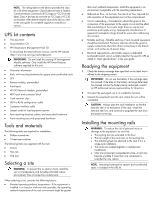
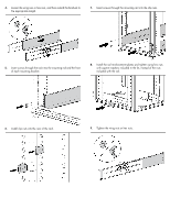
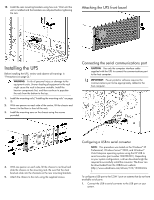
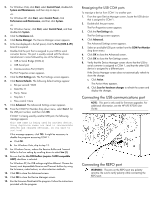
WARNING: To meet the requirements stated in NEC (NFPA 70) Articles 645-10 and 645-11, a UPS installed in a computer equipment room must be connected to a REPO circuit. IMPORTANT: The remote switch must be in the Off (open) position to enable power to the output receptacles. Connecting the ground bonding cable The ground bonding screw is provided as an attachment point for conductors. Use a ground bonding cable if the rack contains any conductors for the purpose of functional grounding or bonding of ungrounded metal parts. The ground bonding cable is not included. NOTE: Wire the connector block using stranded, nonshielded wire (AWG #22 - #18, or equivalent). Separate wire pairs are attached to a single, normally-open contact in a parallel connection. HP recommends using different colors for the positive and negative wires. If a connector becomes disconnected and is reconnected with reversed polarity, a REPO is initiated. To avoid REPO port disconnect: • Minimize wire strain while connecting the REPO port. • Avoid allowing the wires to hang in the rear of the UPS. • Use tie wraps and tie wrap blocks to secure the wires tightly to the rack and the rear of the UPS. Connecting the network cable Connect a standard Ethernet cable between the network connector on the UPS Network Module and a network jack. This connection is used to access the UPS Network Module remotely through the web interface. The UPS Network Module also uses the network connection to communicate to the configured HP Power Protector - Clients and to facilitate SNMP-based monitoring. To configure the UPS Network Module, see "Configuring the UPS Network Module (on page 9)." For more information about the REPO port, see "REPO port" in the user guide. For information about verifying the REPO connection, see "Verifying the REPO port connection" in the user guide.
-
 1
1 -
 2
2 -
 3
3 -
 4
4 -
 5
5 -
 6
6 -
 7
7 -
 8
8 -
 9
9 -
 10
10 -
 11
11 -
 12
12
 |
 |
