HP Scitex FB550 Site Preparation Guide - Page 13
Ventilation and fume extraction, Eye wash station, Storage area for materials
 |
View all HP Scitex FB550 manuals
Add to My Manuals
Save this manual to your list of manuals |
Page 13 highlights
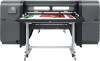
Figure 2-3 FB750 floor layout dimensions Locate the power drop or outlet within 1.5 m (5 ft) from the service end or 3.7 m (12 ft) from the user end to ensure it is able to reach the power inlet. The main and auxiliary power cords connect to inlets on the electronics box at the user end of the printer. An extension cord should not be used with the main power cable, but may be used with the auxiliary power cord if necessary. A power drop from the ceiling may be used. CAUTION: The socket outlet must be installed near the printer and be easily accessible. Ventilation and fume extraction The printer ink and printhead flush emit low levels of fumes and odor. If desired, customers may prepare a solvent-resistant, fire-resistant exhaust fan capable of expelling 1800 CFM of air from the printer to the outside of the building, as well as all necessary duct work prior to the date of printer installation. The customer should work with a heating, ventilation, and air conditioning contractor to ensure that the ventilation system works and complies with local building codes. Eye wash station An eye wash station or suitable eye-washing facilities must be provided to be used in the event of emergency, should chemical splashing occur while system operators are handling inks and printhead flush. The provision of these facilities will help to reduce the risk of irritation and possible damage to the eyes and/or skin. Storage area for materials You will need an area near the printer to store media and ink, and to finish and package prints for shipment or distribution. For best results, media and ink should be stored in a temperature- and humidity-controlled environment similar to the printer's environment. ENWW Facility requirements 7
-
 1
1 -
2
-
3
-
4
-
5
-
6
-
7
-
 8
8 -
 9
9 -
 10
10 -
 11
11 -
 12
12 -
 13
13 -
 14
14 -
 15
15 -
 16
16 -
 17
17 -
 18
18 -
19
-
20
-
21
-
22
-
23
-
24
 |
 |
