HP T1000 IEC-320-C14 HP UPS R/T3000 Installation Instructions - Page 5
Connecting the USB communications port, Connecting the REPO port, Connecting the ground bonding cable
 |
View all HP T1000 IEC-320-C14 manuals
Add to My Manuals
Save this manual to your list of manuals |
Page 5 highlights
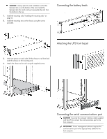
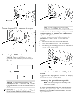
Connecting the USB communications port NOTE: Wire the connector block using stranded, nonshielded wire (AWG #22 - #18, or equivalent). Separate wire pairs are attached to a single, normally-open contact in a parallel connection. HP recommends using different colors for the positive and negative wires. If a connector becomes disconnected and is reconnected with reversed polarity, a REPO is initiated. To avoid REPO port disconnect: • Minimize wire strain while connecting the REPO port. • Avoid allowing the wires to hang in the rear of the UPS. • Use tie wraps and tie wrap blocks to secure the wires tightly to the rack and the rear of the UPS. Connecting the REPO port WARNING: The pins on the REPO port are polarity sensitive. Be sure to verify polarity while connecting the REPO port. WARNING: To meet the requirements stated in NEC (NFPA 70) Articles 645-10 and 645-11, a UPS installed in a computer equipment room must be connected to a REPO circuit. IMPORTANT: The remote switch must be in the Off (open) position to enable power to the output receptacles. For more information about the REPO port, see "REPO port" in the user guide. For information about verifying the REPO connection, see "Verifying the REPO port connection" in the user guide. Connecting the ground bonding cable NOTE: UPS appearance might vary depending on the specific unit installed. The ground bonding screw is provided as an attachment point for conductors. Use a ground bonding cable if the rack contains any conductors for the purpose of functional grounding or bonding of ungrounded metal parts.
-
 1
1 -
 2
2 -
 3
3 -
 4
4 -
 5
5 -
 6
6 -
 7
7 -
 8
8
 |
 |
