HP Vectra VT 6/xxx HP Vectra VT 6/xxx, Familiarization guide - Page 24
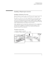
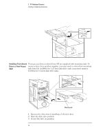
locking lever to lock the processor into place.
 |
View all HP Vectra VT 6/xxx manuals
Add to My Manuals
Save this manual to your list of manuals |
Page 24 highlights
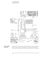
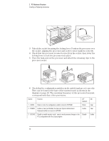
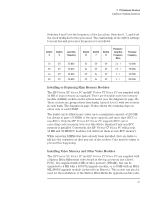
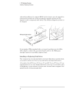
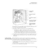
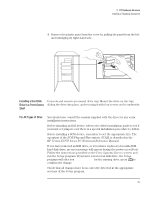
2 PC Hardware Structure Installing or Replacing Accessories 3 Unlock the socket by raising the locking lever. Position the processor over the socket, aligning the processor and socket corner markers correctly. 4 Check that the processor is seated correctly in the socket, then lower the locking lever to lock the processor into place. 5 Place the heat-sink on the processor and attach the retaining clips to the processor socket. 6 Check that the configuration switches in the switch bank are set correctly. They can be found at the base of the system board, as shown in the diagram on page 18. The operating frequency of the processor bus must correspond with that of the processors. Switch: Function: OFF ON (default) 1 - CONFG Retain or clear the configuration which is stored in EEPROM Retain Clear 2 - PSWRD Enable or clear (and disable) the User and System Administrator Passwords which are stored in EEPROM Enable Clear 3 - SECURE Disable or enable security mode - security mode prevents changes to the Disable PC's configuration with the Setup program Enable 20
-
 1
1 -
2
-
3
-
4
-
5
-
6
-
7
-
8
-
9
-
10
-
11
-
12
-
13
-
14
-
15
-
16
-
17
-
18
-
 19
19 -
 20
20 -
 21
21 -
 22
22 -
 23
23 -
 24
24 -
 25
25 -
 26
26 -
 27
27 -
 28
28 -
 29
29 -
30
-
31
-
32
-
33
-
34
-
35
-
36
-
37
-
38
-
39
-
40
-
41
-
42
-
43
-
44
-
45
-
46
-
47
-
48
-
49
-
50
-
51
-
52
-
53
-
54
-
55
-
56
 |
 |
