HP X Class 500/550MHz hp visualize workstation - SDRAM Advantages with the HP - Page 4
The Systems Being Compared
 |
View all HP X Class 500/550MHz manuals
Add to My Manuals
Save this manual to your list of manuals |
Page 4 highlights
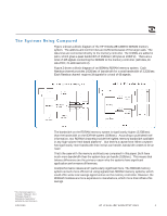
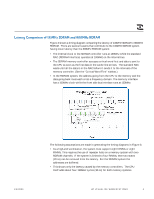
The Systems Being Compared Figure 1 shows a block diagram of the HP VISUALIZE 133MHz SDRAM memory system. The address and control lines are buffered because of the large loads. The data lines are connected directly to the memory controller. The DIMMs are added in pairs, which gives a peak bandwidth of 2GB/sec (16 bytes at 133MHz). There are a total of 165 signals connecting the SDRAM to the memory controller (128 data, 16 data ECC, 21 address/control). Figure 2 shows a block diagram of an 800MHz RDRAM memory system. Each Rambus channel provides 1.6GB/sec of bandwidth for a total bandwidth of 3.2GB/sec. Each Rambus channel requires 34 signals for a total of 68 signals. 2 This information appears in an October 1999 paper, titled "Affordable Power for Workstations Applications," published by Intel Corporation. 1/5/2000 The bandwidth on the RDRAM memory system is significantly higher (3.2GB/sec) than the bandwidth on the SDRAM system (2GB/sec). According to published Intel information, two RDRAM channels provide the highest memory bandwidth available in any high-volume Intel-based platform2. But there's a caveat here: When a system has significantly more bandwidth than its bus can handle, bandwidth ceases to be an issue. That's the case with the memory architectures compared in this paper. Both have much more bandwidth than the system bus can handle (1GB/sec). This means that latency differences are the primary reason why the systems have significant application performance differences. Cost/performance issues aren't particularly significant here. The RDRAM memory system is much more efficient at using signals than SDRAM memory systems, which could offer some cost savings opportunities on the memory controller. However, the RDRAM modules are more expensive to manufacture, which more than offsets this savings. HP VISUALIZE WORKSTATIONS 3
-
 1
1 -
 2
2 -
 3
3 -
 4
4 -
 5
5 -
 6
6 -
 7
7 -
 8
8 -
 9
9 -
 10
10
 |
 |
