Hitachi 32PD7800 Owners Guide - Page 36
OPERATING INSTRUCTIONS continued, SETUP MENU Video mode
 |
View all Hitachi 32PD7800 manuals
Add to My Manuals
Save this manual to your list of manuals |
Page 36 highlights
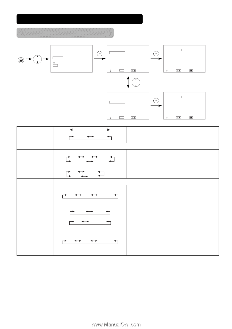
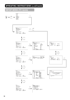
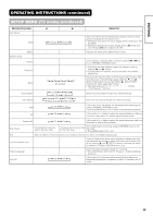
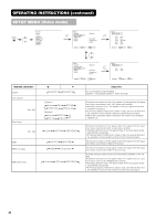
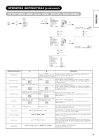
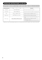
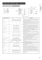
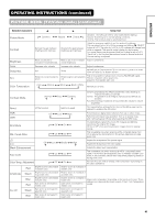
OPERATING INSTRUCTIONS (continued) SETUP MENU (Video mode) MENU Picture Audio Timer Function Setup Language Select OK Set Setup System Color System Video Input RGB1 RGB2 System 1 DVI-STB Component HDTV Select OK Set Return Setup Color System AV1 Auto AV2 PAL AV3 SECAM AV4 PAL AV5 Auto Select Return Exit Selected characters System Color System AV1~AV5 Video Input AV1, AV2 RGB1 RGB2 (1st step) RGB2 (2nd step) Setup System Color System Video Input RGB1 RGB2 System 1 DVI-STB Component HDTV Select OK Set Return Setup Video Input AV1 Auto AV2 Auto Select Return Exit System1 System2 Setup hint Do not change the original setting. (System1 : Europe/Asia, System2 : North America) System1 Auto PAL SECAM NTSC3.58 NTSC4.43 System2 Auto NTSC-M PAL-N PAL-M Auto HDTV SDTV/DVD DVI-PC DVI-STB RGB Component Auto HDTV SDTV/DVD This should correspond to the color system of the signal from the equipment that is connected to AV1~AV5 video input terminal. • Normally, set this to Auto. The system of the input signal will be auto- matically recognized. • If the input signal contains much noise or has a low level at Auto and the operation is found erratic, set this to match the input signal. • When the component signal is received, this would be not available (grayed out). This should correspond to the signal mode of the signal from the equipment that is connected to AV1, 2 video input terminal. • Normally, set this to Auto. The signal mode of the input signal will be automatically recognized. • If the input signal contains much noise or has a low level at Auto and the operation is found erratic, set this to match the input signal. This should correspond to the signal mode of the signal from the equipment that is connected to RGB1 DVI terminal. This should correspond to the signal mode of the signal from the equipment that is connected to RGB2 D-sub terminal. This step should be set only when [Component] is selected on the 1st step. This should correspond to the signal mode of the signal from the equipment that is connected to RGB2 D-sub terminal. • Normally, set this to Auto. The signal mode of the input signal will be automatically recognized. • If the input signal contains much noise or has a low level at Auto and the operation is found erratic, set this to match the input signal. 36
-
 1
1 -
2
-
3
-
4
-
5
-
6
-
7
-
8
-
9
-
10
-
11
-
12
-
13
-
14
-
15
-
16
-
17
-
18
-
19
-
20
-
21
-
22
-
23
-
24
-
25
-
26
-
27
-
28
-
29
-
30
-
 31
31 -
 32
32 -
 33
33 -
 34
34 -
 35
35 -
 36
36 -
 37
37 -
 38
38 -
 39
39 -
 40
40 -
 41
41 -
42
-
43
-
44
-
45
-
46
-
47
-
48
-
49
-
50
-
51
-
52
-
53
-
54
-
55
-
56
-
57
-
58
 |
 |