Hitachi DH18DLP4 Instruction Manual - Page 16
Use batteries correctly in accordance with
 |
UPC - 717709011649
View all Hitachi DH18DLP4 manuals
Add to My Manuals
Save this manual to your list of manuals |
Page 16 highlights
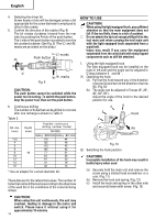
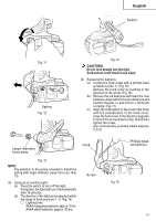
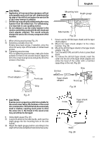
English Arrow " " mark Change lever Fig. 16 Hook main body Indentation Protuberance AAAA batteries Protuberance Indentation Hook cover " " mark Fig. 18 (1) Mount the drill bit. (2) Pull the trigger switch after applying the drill bit tip to the drilling position. (Fig. 19) Fig. 17 NOTE: Do not tighten the screw excessively. Such action could strip the screw threads. Fig. 19 (3) Pushingtherotaryhammerforciblyisnotnecessary at all. Pushing slightly so that drill dust comes out gradually is just sufficient. CAUTION: CAUTION: ⅜ Failure to observe the following can result in When the drill bit touches construction iron bar, battery leakage, rust or malfunction. the bit will stop immediately and the rotary Position the plus (+) and minus (-) terminals hammer will react to revolve. Therefore please grip correctly. the side handle and handle tightly as shown in Replace both batteries at the same time. Do not Fig. 19. mix old and new batteries. Remove exhausted batteries from the hook 4. Rotation only immediately. Turn the change lever fully in the direction of the ⅜ Do not discard batteries together with normal " " mark to set "rotation only". (Fig. 18) trash and do not throw batteries into fire. To drill a wood or metal material using the optional ⅜ Store batteries out of the reach of children. drill chuck and chuck adapter, proceed as follows. ⅜ Use batteries correctly in accordance with the Installing drill chuck and chuck adapter : (Fig. 20) battery specifications and indications. (1) Attach the drill chuck to the chuck adaptor. (2) The part of the SDS-plus shank is the same as the 2. Switch operation drill bit. Therefore, refer to the item of "Mounting ⅜ When the switch trigger is depressed, the tool the drill bit" for attaching it. rotates. When the switch trigger is released, the tool stops. ⅜ The rotational speed of the rotary hammer can be controlled by varying the amount that the switch trigger is pulled. Speed is low when the switch trigger is pulled slightly and increases as the switch Drill chuck trigger is pulled more. ⅜ When releasing the switch trigger, the brake will Chuck adapter Front cap Grip be applied for immediate stopping. 3. Rotation + Hammering Part of SDS-plus shank Turn the change lever fully in the direction of the " " mark to set "rotation + hammering". (Fig. Fig. 20 18) 16
-
 1
1 -
2
-
3
-
4
-
5
-
6
-
7
-
8
-
9
-
10
-
 11
11 -
 12
12 -
 13
13 -
 14
14 -
 15
15 -
 16
16 -
 17
17 -
 18
18 -
 19
19 -
 20
20 -
 21
21 -
22
-
23
-
24
-
25
-
26
-
27
-
28
-
29
-
30
-
31
-
32
-
33
-
34
-
35
-
36
-
37
-
38
-
39
-
40
-
41
-
42
-
43
-
44
-
45
-
46
-
47
-
48
-
49
-
50
-
51
-
52
-
53
-
54
-
55
-
56
-
57
-
58
-
59
-
60
-
61
-
62
-
63
-
64
-
65
-
66
-
67
-
68
-
69
-
70
-
71
-
72
 |
 |
