Homelite UT26HBV User Manual - Page 10
Warning, Tools Needed, Assembling The Blower Tubes, Installing The Vacuum Bag, Installing The Vacuum - won t start
 |
View all Homelite UT26HBV manuals
Add to My Manuals
Save this manual to your list of manuals |
Page 10 highlights
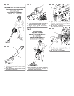
ASSEMBLY PACKING LIST (continued) 2-Cycle Engine Lubricant Operator's Manual NOTE: Read and remove all hang tags and store with your Operator's Manual. WARNING: If any parts are damaged or missing do not operate this product until the parts are replaced. Use of the product with damaged or missing parts could result in possible serious personal injury. WARNING: Do not attempt to modify this product or create accessories not recommended for use with this product. Any such alteration or modification is misuse and could result in a hazardous condition leading to possible serious personal injury. To remove the tubes, use a flat head screwdriver to lift the locking tab, rotate the tubes to unlock them and remove from the blower housing outlet. INSTALLING THE VACUUM BAG See Figures 5 - 6. Remove the nozzle and upper blower tube from the blower by using a flat head screwdriver to lift the locking tab, twisting and removing from blower housing outlet. Unzip the vacuum bag and push the vacuum bag adaptor through the opening opposite the zipper as shown. The wider end of the adaptor will remain on the inside of the vacuum bag when installed properly. Align the raised slots on the vacuum bag adaptor with the raised locking tabs on the blower housing outlet. Push the vacuum bag adaptor onto the housing and twist to lock into place. Rotate the vacuum bag until the shoulder strap is upright. Make sure the vacuum bag is zipped and closed before starting the unit. WARNING: To prevent accidental starting that could cause serious personal injury, always disconnect the engine spark plug wire from the spark plug when assembling parts. TOOLS NEEDED See Figure 2. The following tool (not included or drawn to scale) is needed for assembly: Flat Head Screwdriver ASSEMBLING THE BLOWER TUBES See Figures 3 - 4. Align raised tabs on blower housing outlet to the slots on upper blower tube; slide together and tighten securely by twisting until the tubes snap into the locked position and the lock symbols are aligned. Check tightness after initial use and retighten if needed. NOTICE: When correctly assembled, the tubes are difficult to separate. If they can easily be twisted apart, the tubes are not locked. Continue twisting together until the tubes snap into the locked position. Tubes that are not fully locked together can separate during blower operation. Attach sweeper nozzle to upper blower tube by aligning raised tabs on upper blower tube; slide together and tighten securely by twisting. Check tightness after initial use and retighten if needed. If high velocity nozzle use is desired, attach to sweeper nozzle by aligning raised tab on high velocity nozzle with slot on sweeper nozzle. INSTALLING THE VACUUM TUBES See Figures 7 - 8. WARNING: Contact with rotating impeller blades could result in serious personal injury. Always stop the engine and ensure impeller blades have stopped rotating before opening the vacuum door or installing/changing tubes. Do not put hands or any other object into the vacuum tubes while they are installed on the unit. To install the vacuum tubes: Secure the upper and lower vacuum tubes together by aligning the raised locking tabs with the raised slots. Tap tube assembly on ground until the screw holes in lower tube are in the raised slot of the upper tube. Secure with supplied screws. Depress door tab using a flathead screwdriver and open vacuum inlet door. Align screw mounts on vacuum opening with screws on vacuum tube assembly. Turning clockwise, tighten screws on upper vacuum tube to secure to blower housing. To remove the vacuum tubes: Loosen screws of the upper vacuum tube by turning counterclockwise. Remove the vacuum tube assembly from the blower housing. Close the vacuum inlet cover door securely. Remove the vacuum bag by using a flat head screwdriver to lift the locking tab, rotate to unlock the adaptor and remove. Page 6 - English
-
 1
1 -
2
-
3
-
4
-
 5
5 -
 6
6 -
 7
7 -
 8
8 -
 9
9 -
 10
10 -
 11
11 -
 12
12 -
 13
13 -
 14
14 -
 15
15 -
16
-
17
-
18
-
19
-
20
-
21
-
22
-
23
-
24
-
25
-
26
-
27
-
28
-
29
-
30
-
31
-
32
-
33
-
34
-
35
-
36
-
37
-
38
-
39
-
40
 |
 |
