Honeywell AQ1000TN2 Owners Guide - Page 10
Installation
 |
View all Honeywell AQ1000TN2 manuals
Add to My Manuals
Save this manual to your list of manuals |
Page 10 highlights
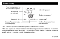
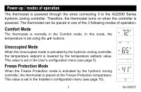
Installation 1. Remove the faceplate from the base by unscrewing the screw underneath the thermostat and tilting the bottom of the faceplate up. Note that the screw remains captive on the base. 2. Insert the wires through the center hole of the base and secure the base to the wall or onto an electrical box. 3. Connect the wires to the terminals (no polarity to observe). Terminal Description 1 TH 2 TH 3 SENSOR 4 SENSOR AQ2000 Series hydronic zoning controller connections External sensor connections for floor temperature measurement (required only if the thermostat is set to F or AF mode; see pages 1 and 8) 4. Set the configuration switches (see next page). 5. Re-attach the faceplate to the base and secure with the captive screw. NOTE: Keep the thermostat's air vents clean and unobstructed at all times. 7 69-2005EF
-
 1
1 -
2
-
3
-
4
-
 5
5 -
 6
6 -
 7
7 -
 8
8 -
 9
9 -
 10
10 -
 11
11 -
 12
12 -
 13
13 -
 14
14 -
 15
15 -
16
-
17
-
18
-
19
-
20
-
21
-
22
-
23
-
24
-
25
-
26
-
27
-
28
-
29
-
30
-
31
-
32
-
33
-
34
-
35
-
36
 |
 |
