Hunter 81030 Owner's Manual - Page 16
Connect wires as shown.
 |
View all Hunter 81030 manuals
Add to My Manuals
Save this manual to your list of manuals |
Page 16 highlights
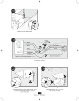
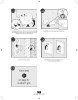
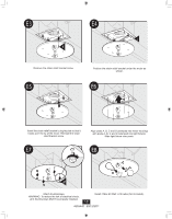
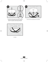
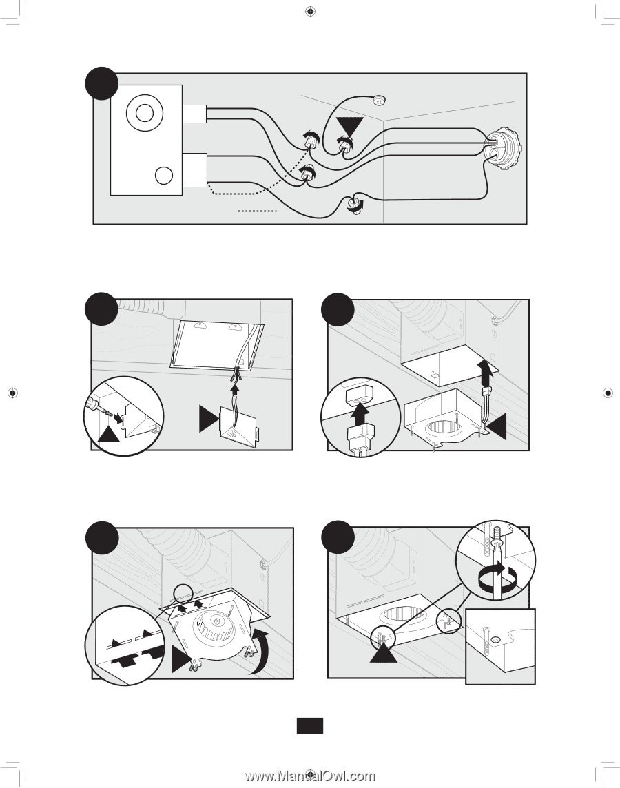
D16 Fan Motor Light 2 Pin Black White White 3 Pin Black Light *Option *Option Fan & Main Light Together Ground Green A Bare Copper Black Main Switch 1 (AC In) White Black Switch 2 (AC In) Connect wires as shown. D17 D18 F G Install the wiring cover plate. D19 H Connect wiring from the motor to the wiring cover plate. D20 H I Reinstall the motor by inserting the tabs and pushing up into position. Make sure the wires are not pinched between the motor and the housing. 16 Secure the motor by tightening the 2 screws. 43034-01 09/12/2011
-
 1
1 -
2
-
3
-
4
-
5
-
6
-
7
-
8
-
9
-
10
-
 11
11 -
 12
12 -
 13
13 -
 14
14 -
 15
15 -
 16
16 -
 17
17 -
 18
18 -
 19
19 -
 20
20 -
 21
21 -
22
-
23
-
24
-
25
-
26
-
27
-
28
-
29
-
30
-
31
-
32
-
33
-
34
-
35
-
36
-
37
-
38
-
39
-
40
-
41
-
42
 |
 |
43034-01
09/12/2011
16
H
D18
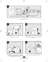
H
D19
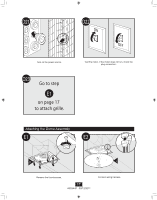
D20
I
A
3 Pin
2 Pin
Fan Motor
Light
Light
Green
Black
Black
White
Black
Black
White
White
Bare Copper
Ground
D16
Main Switch 1 (AC In)
Switch 2 (AC In)
*Option Fan & Main Light Together
*Option
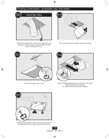
F
D17
G
Reinstall the motor by inserting the tabs and pushing
up into position. Make sure the wires are not pinched
between the motor and the housing.
Connect wiring from the motor to the wiring cover
plate.
Secure the motor by tightening the 2 screws.
Connect wires as shown.
Install the wiring cover plate.