Hunter 81030 Owner's Manual - Page 6
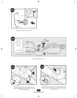
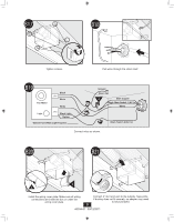
Fan Motor, Light, Green, Black, White, Bare Copper, Ground, Main Switch 1 AC In, Switch 2 AC In,
 |
View all Hunter 81030 manuals
Add to My Manuals
Save this manual to your list of manuals |
Page 6 highlights
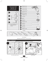
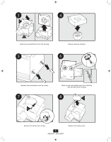
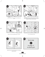
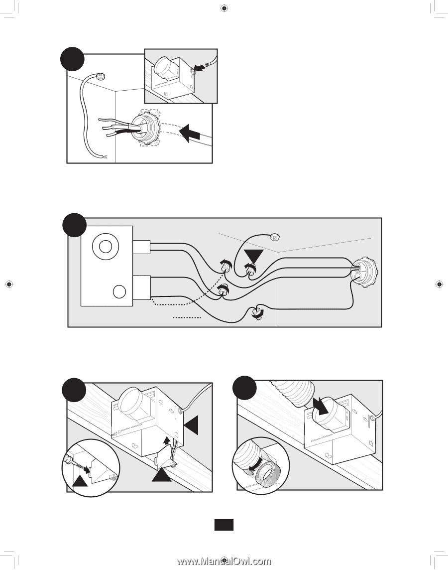
A13 Pull wires through the strain relief. A14 Fan Motor Light 2 Pin Black White White 3 Pin Black Light *Option *Option Fan & Main Light Together Ground Green A Bare Copper Black Main Switch 1 (AC In) White Black Switch 2 (AC In) Connect wires as shown. A15 A16 E F G Install the wiring cover plate. Make sure all wiring connections are inside the box or under the wiring cover plate. Connect 4" duct and vent to the outside. Tape joints. If ducting does not fit securely, an adapter may need to be purchased. 6 43034-01 09/12/2011
-
 1
1 -
 2
2 -
 3
3 -
 4
4 -
 5
5 -
 6
6 -
 7
7 -
 8
8 -
 9
9 -
 10
10 -
 11
11 -
 12
12 -
13
-
14
-
15
-
16
-
17
-
18
-
19
-
20
-
21
-
22
-
23
-
24
-
25
-
26
-
27
-
28
-
29
-
30
-
31
-
32
-
33
-
34
-
35
-
36
-
37
-
38
-
39
-
40
-
41
-
42
 |
 |
43034-01
09/12/2011
6
A
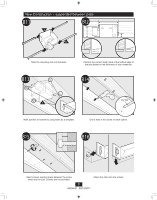
3 Pin
2 Pin
Fan Motor
Light
Light
Green
Black
Black
White
Black
Black
White
White
Bare Copper
Ground
A14
Main Switch 1 (AC In)
Switch 2 (AC In)
*Option Fan & Main Light Together
*Option
A13
°
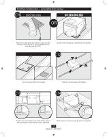
A16
Connect 4” duct and vent to the outside. Tape joints.
If ducting does not fit securely, an adapter may need
to be purchased.
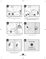
A15
E
F
G
Install the wiring cover plate. Make sure all
wiring connections are inside the box or under
the wiring cover plate.
Connect wires as shown.
Pull wires through the strain relief.