Icom IC-A6 Instruction Manual
Icom IC-A6 Manual
 |
View all Icom IC-A6 manuals
Add to My Manuals
Save this manual to your list of manuals |
Icom IC-A6 manual content summary:
- Icom IC-A6 | Instruction Manual - Page 1
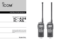
INSTRUCTION MANUAL VHF AIR BAND TRANSCEIVER iA24 iA6 This device complies with Part 15 of the FCC Rules. Operation is subject to the condition that this device does not cause harmful interference. IC-A24 IC-A6 - Icom IC-A6 | Instruction Manual - Page 2
accessories other than those specified may result in RF exposure levels exceeding the FCC requirements for wireless RF exposure.; Belt Clip (MB- 86/103), Rechargeable Ni-MH Battery Pack (BP-210N) and Alkaline Bat- tery Case (BP-208N). • DO NOT operate the radio without a proper antenna attached - Icom IC-A6 | Instruction Manual - Page 3
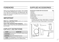
INSTRUCTION MANUAL- This in- struction manual contains important operating instructions for the IC-A24/A6. Accessories included with the transceiver: Qty. q Antenna 1 w Belt clip 1 e Handstrap 1 r Battery pack* or battery case 1 t Wall charger 1 y Carrying case 1 u Headset adapter - Icom IC-A6 | Instruction Manual - Page 4
a ringing in your ears, reduce the volume level or discontinue use. The use of non-Icom battery packs/chargers may impair NEVER connect the transceiver to an AC outlet or to a transceiver performance and invalidate the warranty. power source of more than 11.5 V DC. Such a connection will - Icom IC-A6 | Instruction Manual - Page 5
(U.S.A. version only 24 7 BATTERY PACKS 25 - 27 I Battery charging 25 I Battery cautions 25 I Optional battery case 26 I Optional battery chargers 27 8 CLONING 28 9 TROUBLESHOOTING 29 10 SPECIFICATIONS 30 11 OPTIONS 31 12 QUICK REFERENCE 32 - 33 13 OPTIONAL HEADSET CONNECTION 34 iv - Icom IC-A6 | Instruction Manual - Page 6
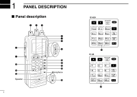
1 PANEL DESCRIPTION I Panel description e rt w q !7 !6 !5 Speaker y u i o !0 !1 !2 !3 Microphone !4 1 IC-A24 WX-ALERT IC-A6 !7 WX-ALERT !7 - Icom IC-A6 | Instruction Manual - Page 7
frequencies to back or front. i POWER SWITCH [PWR] (pgs. 9, 28) ➥ Push and hold for 2 sec. to turn the power ON or OFF. ➥While pushing and holding [MR•MW], push [PWR] to enter the cloning function mode. o EXTERNAL SPEAKER AND MICROPHONE JACKS [MIC/SP] (p. 34) Connects an OPC-499 HEADSET ADAPTER - Icom IC-A6 | Instruction Manual - Page 8
Push for 2 sec. to select the 121.5 MHz emergency frequency. • DC POWER CONNECTION IC-A24/A6 CP-20 (for 11 24 V) (optional) !4 DC POWER JACK Connect the AC adapter or optional cable to charge the battery pack or to operate by external power supply. (see right illustration) !5 MEMORY MODE KEY [MR - Icom IC-A6 | Instruction Manual - Page 9
to select the CDI display from the CDI display in NAV band. (p. 19)*1 PANEL DESCRIPTION 1 Push , then push [5•DUP-W] to set the duplex 1 frequency in NAV band for U.S.A. version only. (p. 24)*1 Push , then channel as a "TAG" channel. (p. 17) *1 These functions available on the IC-A24 only. 4 - Icom IC-A6 | Instruction Manual - Page 10
squelch opens. r DUPLEX INDICATOR (IC-A24 only) (p. 24) ➥"DUP" appears when the duplex function is activated in NAV mode. ➥"DUP" blinks while setting the duplex frequency. t LOW BATTERY INDICATOR (p. 10) ➥ Appears when the battery is nearing exhaustion. The attached battery pack requires recharging - Icom IC-A6 | Instruction Manual - Page 11
desired course is located on a VOR radial in CDI mode. !0 MEMORY BANK NUMBER INDICATOR (p. 12) Shows the selected memory bank number. !1 OVERFLOW INDICATOR (IC-A24 only) (pgs. 18-22) Appears when the deviation between the desired course and flying course is over 10 degrees. !5 TO-FROM INDICATOR - Icom IC-A6 | Instruction Manual - Page 12
2 ACCESSORY ATTACHMENT D Antenna CAUTION: DO NOT transmit without an antenna. Other- wise the transceiver may be damaged. Insert the supplied antenna into the antenna connector and screw down the antenna as shown below. D Belt clip Conveniently attaches to your belt. Attach the belt clip with the - Icom IC-A6 | Instruction Manual - Page 13
transceiver has a noise squelch circuit to mute undesired 2 q Push [PWR] for 2 sec. to turn power ON, then push [CLR•DEL] to select the frequency 120.000 MHz: Push • 125.300 MHz: Push The U.S.A. version has VHF marine WX (weather) channel receiving capability for flight planning. q Push , then - Icom IC-A6 | Instruction Manual - Page 14
: Transmitting without an antenna may damage the transceiver. NOTE: To prevent interference, listen on the frequency before transmitting. If the frequency is busy, wait until the channel is clear. q Set the desired frequency in COM band using [DIAL] or keypad. • COM band frequency range: 118.00-136 - Icom IC-A6 | Instruction Manual - Page 15
battery indicator Low battery indicator appears Low battery indicator when the battery power has decreased to a specified level. The attached battery recall function stores the last 10 frequencies used. The function stores frequencies when the frequency is programmed and transmitted on (except memory, - Icom IC-A6 | Instruction Manual - Page 16
--10' is Max. level. NEVER operate the transceiver with a headset at high volume levels for long period. A ringing in your ears may occur. If so, reduce the monitor level or discontinue use. The IC-A24 and IC-A6 can quickly gain access to the 121.5 MHz emergency frequency. This function can be acti - Icom IC-A6 | Instruction Manual - Page 17
in the selected BANK, no memory CH. selection is available. NOTE: Comments appear first when programmed, how- Memory mode Frequency mode ever, the transceiver can be programmed by your dealer to show the operating frequency first. Push [MR•MW] to dis- play the comment in this case. 12 - Icom IC-A6 | Instruction Manual - Page 18
4 MEMORY OPERATION I Programming a memory channel The transceiver has 200 (20 CH. × 10 BANK) memory channels for storage of often-used frequencies. q Push [CLR•DEL] to select the frequency mode, if necessary. w Select the desired frequency. • Push , then push [ENT•WX] to select a weather channel.* - Icom IC-A6 | Instruction Manual - Page 19
can display a 6-character names instead of the programmed frequency. 1 1, Q, Z 2 2, A, B, C 3 3, D, E, F 4 4, G, H, I 5 5, J, K, L 6 6, M, N, O 4 q Rotate [DIAL] to select the desired frequency in the frequency mode. w Push , then push [MR•MW] to program the contents into the selected memory - Icom IC-A6 | Instruction Manual - Page 20
• EXAMPLE: Programming 125.000 MHz into memory BANK 1/ memory channel 17 with "AIR-23" as a comment. Push Push Push Push Push Push Push Push Push Push NOTE: Push [0•BANK], then rotate [DIAL] to select the BANK number, if desired. Push [CLR•DEL] to continue memory name programming. 15 - Icom IC-A6 | Instruction Manual - Page 21
The U.S.A. version has 3 scan types to suit your needs. The q Push [CLR•DEL] to select the frequency mode. non-U.S.A. versions have 2 scan types. w Push [SQL•WX-ALERT] to set the squelch level to the point COM BAND SCAN where noise is just muted. e Push , then push [ANL•SCAN] to start the scan - Icom IC-A6 | Instruction Manual - Page 22
5 SCAN OPERATION I Weather channel scan (U.S.A. version only) q Push , then push [ENT•WX] to select a weather channel. w Set squelch to the point where noise is just muted. e Push , then push [ANL•SCAN] to start the scan. • When a signal is received, the scan pauses until it disappears. • To change - Icom IC-A6 | Instruction Manual - Page 23
6 VOR NAVIGATION (IC-A24 ONLY) I VOR indicators COM BAND (118.00 136.975 MHz) NAV BAND (108.00 117.975 MHz) DVOR MODE 5 Course indicator 6 To-from flag indicator Push [F] then [1 DVOR]. Push [F] then [4 CDI]. CDI MODE General VOR equipment Function display of the IC-A24 Course indicator - Icom IC-A6 | Instruction Manual - Page 24
To select the DVOR mode When entering the NAV band, 108.000-117.975 MHz, the IC-A24 selects the DVOR mode automatically. To show your aircraft's direction to (or from) the VOR station, push , then push [1•DVOR] to select the DVOR mode. Operating frequency can not be changed. Course deviation needle - Icom IC-A6 | Instruction Manual - Page 25
frequency cannot be changed. To set the operating frequency, select the DVOR mode in advance. NOTE: For U.S.A. version only IC-A24's VOR and CDI Navigation features are supplemental aids to navigation only, and are not intended to be a substitute for accurate (primary) VOR/CDI or landing service - Icom IC-A6 | Instruction Manual - Page 26
6 VOR NAVIGATION (IC-A24 ONLY) THE AIRCRAFT IS ON COURSE THE AIRCRAFT IS OFF COURSE NOTE: The course deviation indicator appears when the aircraft is off course. In this - Icom IC-A6 | Instruction Manual - Page 27
NAVIGATION (IC-A24 ONLY) I Entering a desired course I Crosschecking position The IC-A24 shows not only the deviation from the VOR sta- q Select 2 VOR stations on your aeronautical chart. tion but the deviation from the desired course. w Push the keypad or rotate [DIAL] to set the frequency of - Icom IC-A6 | Instruction Manual - Page 28
6 VOR NAVIGATION (IC-A24 ONLY) EXAMPLE: Entering the desired course bearing 65° to a VOR station. CROSSCHECKING POSITION VORTAC OLYMPIA 113.4 Ch 81 OLM 310 320 330 340 350 300 - Icom IC-A6 | Instruction Manual - Page 29
6 VOR NAVIGATION (IC-A24 ONLY) I Duplex operation (U.S.A. version only) D Operating the duplex function q Set the desired frequency in NAV band. • NAV band frequency range: 108.00-117.975 MHz The duplex function allows you to call a flight service station while receiving a VOR station. The duplex - Icom IC-A6 | Instruction Manual - Page 30
charging. NEVER use another manufacture's adapters. • Use the specified chargers (BC-119N, BC-121N and BC-144N). NEVER use another manufacture's charger. CAUTION! NEVER insert battery pack/transceiver (with the battery pack attached) with wet or soiled into the charger. This may result in corrosion - Icom IC-A6 | Instruction Manual - Page 31
the battery case from the transceiver. w Install 6 × AA(R6) size Alkaline batteries. • Be sure to observe the correct polarity. DO NOT charge BP-210N more than 12 hours. Otherwise, BP-210N will be damaged. BP-210N must be charged for 8-12 hours only. IC-A24/A6 with attached battery pack Turn - Icom IC-A6 | Instruction Manual - Page 32
6 battery packs to be charged simultaneously. The following are additionally required. • Six AD-101 charger adapters. • An AC adapter (BC-124) or the DC power cable (OPC-656). NOTE: Attach the spacer (Spacer B/C) to the adapter (Spacer A) with orientation as illustrated below. Turn power OFF IC-A24 - Icom IC-A6 | Instruction Manual - Page 33
data from IC-A24 to IC-A6, programmed data from one transceiver to another when the data contains the NAV band data. In such case, transceiver, or, data from PC to a transceiver using the cloning error may occur. optional CS-A24 cloning software. D Transceiver to transceiver cloning q Connect - Icom IC-A6 | Instruction Manual - Page 34
9 TROUBLESHOOTING If your transceiver seems to be malfunctioning, please check the following points before sending it to a service center. PROBLEM POSSIBLE CAUSE SOLUTION REF. No power comes on. • The battery is exhausted. • Bad connection for the battery pack. • Recharge the battery pack. - Icom IC-A6 | Instruction Manual - Page 35
SPECIFICATIONS D General D Transmitter • Frequency coverage (MHz): TX 118.000 to 136.975 RX 108.000 to 136.975*1 WX 161.650 to 163.275*2 *1: IC-A24 only, IC-A6 • Weight : Approx. 180 g (6.35 oz) (Without the battery pack and antenna.) COM (AM 6dB S/N): Less than -6 dBµ typical WX (FM 12dB - Icom IC-A6 | Instruction Manual - Page 36
socket*. ➥Operates IC-A24/A6 through a cigarette lighter socket*. *Both 12 V and 24 V batteries are available. • OPC-656 DC POWER CABLE FOR BC-121N WITH DC Charges the battery pack using 13.8 V power source instead of the AC adapter for BC-121N. D OTHER OPTIONS • OPC-499 HEADSET ADAPTER CABLE When - Icom IC-A6 | Instruction Manual - Page 37
32 OPERATION GUIDE iA24/A6 n VOR NAVIGATION (p. 22) Entering a desired course. q Push keypad or rotate [DIAL] to set the frequency for the desired VOR station. DEL] to cancel the scanning. QUICK 12 REFERENCE Important operating instructions are summed up in this and the following page for your - Icom IC-A6 | Instruction Manual - Page 38
the fre- quency mode or push , then push [ENT WX] to select WX CH* mode. w Select the desired frequency or WX CH.* e Push , then push [MR MW] to enter memory programming mode. "M", BANK and memory numbers blink on the display. r Rotate [DIAL] (or push keypad) to select a desired memory - Icom IC-A6 | Instruction Manual - Page 39
adapter, the transceiver outputs your transmitted voice to the headset for monitoring. See "I Side tone function "(p. 11) when setting the side tone level. PTT switch Use a PTT switch with a 3.5 mm (1/8") diameter plug, if required. OPC-499 HEADSET (Must be purchased separately) 12 13 IC-A24 - Icom IC-A6 | Instruction Manual - Page 40
A-6403D-1EX Printed in Japan © 2004 Icom Inc. 1-1-32 Kamiminami, Hirano-ku, Osaka 547-0003, Japan
-
 1
1 -
 2
2 -
 3
3 -
 4
4 -
 5
5 -
 6
6 -
 7
7 -
8
-
9
-
10
-
11
-
12
-
13
-
14
-
15
-
16
-
17
-
18
-
19
-
20
-
21
-
22
-
23
-
24
-
25
-
26
-
27
-
28
-
29
-
30
-
31
-
32
-
33
-
34
-
35
-
36
-
37
-
38
-
39
-
40
 |
 |
INSTRUCTION MANUAL
iA6
iA24
VHF AIR BAND TRANSCEIVER
This device complies with Part 15 of the FCC
Rules. Operation is subject to the condition
that this device does not cause harmful inter-
ference.
IC-A24
IC-A6