Intel AXXRMS2AF080 Hardware User Guide - Page 25
Flash ROM, Boot Strap ROM (SEEPROM), NVSRAM, Diagnostic Components, LED Placement and Function
 |
View all Intel AXXRMS2AF080 manuals
Add to My Manuals
Save this manual to your list of manuals |
Page 25 highlights
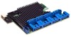
• Allows multiple initiators to address a single target (in a fail-over configuration) through an expander. For more information, see http://www.lsi.com/. Note: Some of these chip features may not be supported by Intel® Integrated RAID Module RMS2AF040 and RMS2AF080. Flash ROM An 16-MB CFI-compliant flash ROM is used to accommodate RAID firmware and RAID BIOS Console 2 OpROM. Boot Strap ROM (SEEPROM) The serial bootstrap ROM is used to configure the LSI* LSISAS2008 Processor Chip before the server board configures the PCI Express* registers. The bootstrap ROM sets the Phase Lock Loop (PLL) dividers, bootstrap configuration, and so on. NVSRAM A 32-KB NVSRAM is used to store disk and drive setup information. Diagnostic Components LED Placement and Function The Intel® Integrated RAID Module RMS2AF040 and RMS2AF080 contain the following LEDs: • One surface-mounted heartbeat ("DS1B1: SAS_HB_LED") LED (Green Color) to indicate LSISAS2008 activity. • Another surface-mounted system error ("DS1B2: SAS_FLT_LED") LED (Amber Color) to indicate a board error. SAS/SATA Connectors The Intel® Integrated RAID Module RMS2AF040 and RMS2AF080 provides four and eight internal SAS/SATA signal port connectors. Intel® Integrated RAID Module RMS2AF040 and RMS2AF080 Hardware User's Guide 15
-
 1
1 -
2
-
3
-
4
-
5
-
6
-
7
-
8
-
9
-
10
-
11
-
12
-
13
-
14
-
15
-
16
-
17
-
18
-
19
-
 20
20 -
 21
21 -
 22
22 -
 23
23 -
 24
24 -
 25
25 -
 26
26 -
 27
27 -
 28
28 -
 29
29 -
 30
30 -
31
-
32
-
33
-
34
-
35
-
36
-
37
-
38
-
39
-
40
-
41
-
42
-
43
-
44
-
45
-
46
-
47
-
48
-
49
-
50
 |
 |
