Intel AXXRMS2AF080 Hardware User Guide - Page 7
List of s
 |
View all Intel AXXRMS2AF080 manuals
Add to My Manuals
Save this manual to your list of manuals |
Page 7 highlights
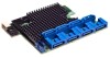
List of Figures Figure 1. Installing the Barrel Standoff 8 Figure 2. Installing Intel® Integrated RAID Module RMS2AF0x0 8 Figure 3. Connecting Cable between the RAID Module and Drives/Backplane 9 Figure 4. Card Layout...11 Figure 5. RMS2AF040 Hardware Block Diagram 13 Figure 6. RMS2AF080 Hardware Block Diagram 14 Figure 7. Intel® Integrated RAID Module RMS2AF0x0 SAS/SATA Connectors 16 Figure 8. SAS/SATA Interface 16 Figure 9. SAS/SATA Cable ...17 Figure 10. PCI Interface ...18 Intel® Integrated RAID Module RMS2AF040 and RMS2AF080 Hardware User's Guide vii
-
 1
1 -
 2
2 -
 3
3 -
 4
4 -
 5
5 -
 6
6 -
 7
7 -
 8
8 -
 9
9 -
 10
10 -
 11
11 -
 12
12 -
13
-
14
-
15
-
16
-
17
-
18
-
19
-
20
-
21
-
22
-
23
-
24
-
25
-
26
-
27
-
28
-
29
-
30
-
31
-
32
-
33
-
34
-
35
-
36
-
37
-
38
-
39
-
40
-
41
-
42
-
43
-
44
-
45
-
46
-
47
-
48
-
49
-
50
 |
 |

Intel® Integrated RAID Module RMS2AF040 and RMS2AF080 Hardware User’s Guide
vii
List of Figures
Figure 1. Installing the Barrel Standoff
......................................................................................
8
Figure 2. Installing Intel
®
Integrated RAID Module RMS2AF0x0
..............................................
8
Figure 3. Connecting Cable between the RAID Module and Drives/Backplane
........................
9
Figure 4. Card Layout
..............................................................................................................
11
Figure 5. RMS2AF040 Hardware Block Diagram
....................................................................
13
Figure 6. RMS2AF080 Hardware Block Diagram
....................................................................
14
Figure 7. Intel
®
Integrated RAID Module RMS2AF0x0 SAS/SATA Connectors
.....................
16
Figure 8. SAS/SATA Interface
.................................................................................................
16
Figure 9. SAS/SATA Cable
.....................................................................................................
17
Figure 10. PCI Interface
..........................................................................................................
18